
Maf Scaling table
 Dec 16, 2006, 11:29 AM
#1

Maf Scaling table
OK, I wanted to start a thread on this to get input from everybody on what they think. I spent the last day or so making a spreadsheet based on data from the DSM-ECU list and the DSMLink forums along with the data from my 05 ROM for the Maf scaling table.
My spreadsheet is called Evo Maf.xls and it is a bit of a long read and tough to understand if you haven't seen the data before, but I'm hoping that some more people can jump in and provide feedback. My point for doing this was to get our Maf scaling table scaled correctly in ECUFlash so that people can easily tune aftermarket intakes, filters, or any other mod that may alter the MAF's airflow reading, and thus calibration.
There is still a lot that I need to learn, but I am hoping that others can help. I know that MalibuJack and awdgsx have already done a lot with the tables and their scalings.
Attached is my attempt at scaling and explanations for them. My spreadsheet is Evo Maf.xls. The others are a couple that I used for my analysis and I have added for your reference.
A couple of pictures from my spreadsheet:
Maf curve using Hz and L/Hz with preliminary scaling

New scaling shown in Ecuflash
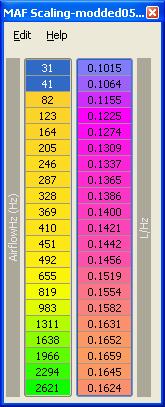
EDIT: Post #54 has the newer, updated spreadsheet with the correct scaling for the table shown above. The Hz scales to 1600Hz.
Eric
My spreadsheet is called Evo Maf.xls and it is a bit of a long read and tough to understand if you haven't seen the data before, but I'm hoping that some more people can jump in and provide feedback. My point for doing this was to get our Maf scaling table scaled correctly in ECUFlash so that people can easily tune aftermarket intakes, filters, or any other mod that may alter the MAF's airflow reading, and thus calibration.
There is still a lot that I need to learn, but I am hoping that others can help. I know that MalibuJack and awdgsx have already done a lot with the tables and their scalings.
Attached is my attempt at scaling and explanations for them. My spreadsheet is Evo Maf.xls. The others are a couple that I used for my analysis and I have added for your reference.
A couple of pictures from my spreadsheet:
Maf curve using Hz and L/Hz with preliminary scaling
New scaling shown in Ecuflash
EDIT: Post #54 has the newer, updated spreadsheet with the correct scaling for the table shown above. The Hz scales to 1600Hz.
Eric
Last edited by l2r99gst; May 28, 2008 at 04:09 PM.
 Dec 16, 2006, 03:08 PM
#3
Oh and the AirflowHZ value correlated exactly to the MUT conversion formula I used for scaling.. Therefore I'm fairly certain that the left column would be in HZ (as if that wasn't already known)
The big issue is the relationship of the MAF SIZE parameter, MAF Scaling, and MAF Smoothing..
Also, in your spreadsheet you compared the plot you did, with data from a flow bench, the flow bench numbers are a good example of the anomolous reading you can get when you don't flow test the entire induction setup from airbox to intake pipe, and just the MAF itself, as at a particular frequency, you get those anomolous readings..
That graph validates my observations of aftermarket cone filters and intakes that tend to run a bit rich down low, then lean at the midrange, then a bit rich again at higher RPM if airflow could actually read over 1500hz (which it generally didn't on a stock car with an aftermarket intake and open element filter)
Last edited by MalibuJack; Dec 16, 2006 at 03:13 PM.
Dec 16, 2006, 03:27 PM
#4
Once I get a little more time and we can nail down the correct scalings, then I can get a forumla for mass airflow from Hz, baro, and temp.
I already calculated a forumla from my spreadsheet data, but didn't include it right now, since I know the scalings are probably off. I am going to put the forumlas in EvoScan or Mitsulogger to log compared to the Scantech OBD-II logger to correlate the g/s airflows. That will let me get my scalings better.
That's also the reason why I didn't post the screenshots of my scalings. I know they will probably be adjusted and I didn't want to post anything yet so no one puts it in ECUFlash now and thinks it's correct.
Eric
Dec 16, 2006, 03:31 PM
#5

Thanks Eric.
I found your data interesting and followed through each step.
I find the logic impeccable.
On a personal note, if I ever experiment with a speed density conversion on the Evo you've given me an idea of another way to do it... rather than simply take the manifold pressure in KPa and use it as load which would overfuel in the low VE areas of idle and underfuel at peak torque at high VE, and require changes to possibly undocumented idle maps, I'd use this table as my VE map. I previously used an 8 point coarse MAF scaling table on an Apexi Power FC that took a MAF voltage and scaled it from 77% at idle, to 115% at peak torque, back to 100% at peak power. This was enough to model the entire VE of the engine quite closely. Then the AFR values in the fuel table matched the wideband AFR and I had simulated a MAF sensor using a simple box that took MAP*RPM and chucked out a voltage that was proportional. There is the potential to do this in software by putting the MAP signal into the location that MAF Hz should be.
Dec 16, 2006, 03:41 PM
#6
Yes, I don't see why you couldn't use it as a VE map.
In DSMLink, one of their dialog boxes allowed us to alter the maf scaling per HZ and the next tab was the VE of the engine. I wonder if DSMLink was actually using one table for both. I thought it was two different tables, as the Airflow table had 9 adjustment points by Hz and the VE table had 17 adjustment points by RPM.
Eric
Last edited by l2r99gst; Dec 16, 2006 at 03:43 PM.
Dec 16, 2006, 03:54 PM
#7
Equations for mass airflow
This is how I am going to try to nail down the scalings better:
From my spreadsheet, if you graph the L/s vs Hz from my original scaling guesses, you will get a graph that looks like this:

To find the mass airflow from the L/s value, you just have to multiply by the density of air, using the equation PV=nRT.
n/v=P/RT
P is baro that we log in our loggers
T is air intake temperature that we log in our loggers
So, skipping past all of the boring math, I can add these two lines to Mitsulogger:
<Request LogReference="AirDensity" RequestID="FF" Eval="Baro/(((AirTemp-32)*5/9+273.15)*8.132)*28.9" Unit="g/L" Logged="y" Response="2"/>
<Request LogReference="Mass Airflow" RequestID="FF" Eval=".167*AirFlow*AirDensity-7.1736*AirDensity" Unit="g/s" Logged="y" Response="2"/>
Edit: Actually, the second equation above for mass airflow wasn't set with an intercept of 0, so the equation will be off a bit. Actually, though, I found a much better fit from 0-2000Hz (R squared of .9997): y = 0.0712x^1.1131
We can compare the Hz and g/s values from Mitsulogger with a g/s log from OBD-II, like Scantech and adjust the scaling accordingly.
Eric
From my spreadsheet, if you graph the L/s vs Hz from my original scaling guesses, you will get a graph that looks like this:
To find the mass airflow from the L/s value, you just have to multiply by the density of air, using the equation PV=nRT.
n/v=P/RT
P is baro that we log in our loggers
T is air intake temperature that we log in our loggers
So, skipping past all of the boring math, I can add these two lines to Mitsulogger:
<Request LogReference="AirDensity" RequestID="FF" Eval="Baro/(((AirTemp-32)*5/9+273.15)*8.132)*28.9" Unit="g/L" Logged="y" Response="2"/>
<Request LogReference="Mass Airflow" RequestID="FF" Eval=".167*AirFlow*AirDensity-7.1736*AirDensity" Unit="g/s" Logged="y" Response="2"/>
Edit: Actually, the second equation above for mass airflow wasn't set with an intercept of 0, so the equation will be off a bit. Actually, though, I found a much better fit from 0-2000Hz (R squared of .9997): y = 0.0712x^1.1131
We can compare the Hz and g/s values from Mitsulogger with a g/s log from OBD-II, like Scantech and adjust the scaling accordingly.
Eric
Last edited by l2r99gst; Dec 17, 2006 at 04:00 PM.
Trending Topics
Dec 16, 2006, 04:37 PM
#8
Cool.. this is where the value of Mitsulogger really comes into play, with some of these complex calculations..
I don't think anyone really grasps the immense value of this new data..
This was more or less the "missing link"..
I don't think anyone really grasps the immense value of this new data..
This was more or less the "missing link"..
Last edited by MalibuJack; Dec 16, 2006 at 04:41 PM.
Dec 16, 2006, 04:47 PM
#9
Here's another observation, since the value for MAF HZ is a word of data,
It might be possible to use a GM MAF Sensor without a converter since it outputs a frequency also, only the output frequency of the GM sensor is much higher, but I wonder if someone has a plot of the GM sensor output with relation to the same data, if you do, you might then be able replace the values in the left axis to use the GM sensor instead.
FWIW I'm not a fan of Speed Density and think its probably not the best option to "Take a step backwards" by using it.
Dec 16, 2006, 06:56 PM
#10
I think the GM MAF frequencies correlate directly to a mass airflow though, not a volumetric airflow. So, what you stated may very well be possible, but I think that we would have to lock the baro and airtemp, similar to the way the MAF translator did.
I used the MAF translator on my DSM and I thought it worked great once calibrated. It would be nice to have GM MAF support with the stock ECU, though.
Eric
I used the MAF translator on my DSM and I thought it worked great once calibrated. It would be nice to have GM MAF support with the stock ECU, though.
Eric
Dec 16, 2006, 08:33 PM
#11
Thats actually the easy part.. a potentiometer or resistor to replace one or both the Baro and AIT sensor to output a constant value is all thats needed. The only additional item required would be a plug and play harness to make the swap a no-brainer.
Oh, and you are correct, the GM sensor does do Mass Airflow, as a hot-wire sensor, it uses the cooling effect to calculate the air mass, since humidity, air temp, altitude, air density in general are all factors in how much it cools the sensor (the more molecules go by, the more heat it takes away) the resulting output is air mass..
Some of the newer GM sensors actually do have AIT sensors, but I don't think their used for anything but cold start and some sort of enrichment (plus OBD-II and Emission stuff) in a GM ECU, but I could be wrong as I haven't done any research on it since my 97 Z28 SS or my 91 Vette (both were supercharged)
Last edited by MalibuJack; Dec 16, 2006 at 08:55 PM.
Dec 17, 2006, 06:20 AM
#12

This is really good info here. IF the GM maf can be used directly, and the table rescaled along with the correct values, then a very easy tunable blow through is possible.
On the AIT ( if this is intake air temp ) this is something that Nissan has used for a long time. As MalibuJack said, it is definitely used on cold start, but also as an adjustment under WOT to compensate for gross temperature difference ie 15F and 100 F. That way you are not running lean at WOT.
The Mitsu code has to incorporate this too. And the table for scaling it has to exist somewhere.
Milburn
Dec 17, 2006, 07:20 AM
#13
Mitsubishi's code does take that into account, I think there's already a documented table for it.
Unfortunately its a two-fold issue, the first is since our sensor is a VAF sensor, it requires that temp to complete the mass air calculation, so by using the sensor, you end up "Double compensating" for it. Same with the Baro sensor. Fortunately there's a compensation table also used.
Now, on the Evo, the lookups are almost exclusively load based, and the load cells track with VE, which is primarily Mass air, so as long as the MAF sensor reports accurate data (on a conversion with the AIT and MAF locked) it should still work okay and not run lean at WOT.
The problem is cold start, both the MAF sensor and intake pipes have to get up to temp, plus it sometimes has to shed condensation off the sensor and pipes, that is where the minor cold drivability issues comes from when doing a blowthrough conversion. The reason I use the Ford sensor over the GM sensor is its less prone to collecting as much condensation requiring a longer time for warmup.
Dec 17, 2006, 01:43 PM
#14
Evolved Member

Hi
Ok I might have completly missed the point here, but I thought I'd just apply the /6.25 to the unit16 scaling in the map deffinition (& * 6.25 in the reverse direction). This of course changes the data displayed in ECUflash window. I had a look through the other tables and the idle stepper look up table now makes a bit more sense.
If I've just done the really obvious, just let me know. But the scales do look nicer.
MB
Dec 18, 2006, 06:57 AM
#15
Evolved Member
iTrader: (19)
Join Date: Sep 2005
Location: Butthole, MA
Posts: 834
Likes: 0
Received 0 Likes
on
0 Posts
So I'm a little lost here.
I think I understand what you're trying to do but I think there's a gap of info I'm missing.
I see the maf scaling chart that you posted...and for your intake that may be fine. Certain voltage for a certain flow rate.
However, if I open ecuflash my MAF scaling is based on load/units not airflow/voltage.
What am I missing? I have a Dejon-tool intake so I know my MAF readings are pretty skewed. My car drops into open loop at idle all the time. I'd really like to get this ironed out with my closed maps.