
Meth Failsafe and Patches
 Jan 3, 2008, 07:58 PM
#196

Actually the load threshold doesn't apply to the ADC0F selection code.
Jamie, can you do:
1) turn car on
2) ensure 0v is being applied to ADC0F
3) hold down the autoics button to disable altmaps - this should stop the flashing light
4) apply 5v to ADC0F - this should start the flashing ICS light
5) wait a little bit (10 secs, just for the system to sort itself out)
6) apply 0v to ADC0F - this should stop the flashing ICS light.
let me know!
edit - can you also send me a log, of ADC0F just hooking up 5v and disconnecting the 5v. Only log the ADC0F so we get the fastest possible logging speed
 Jan 3, 2008, 08:58 PM
#203
So you think the ICS was activated when I flashed it??(I dont use my ICS so its always off) What about the cars with ICS code but no ICS buttons? will this be an issue that they would have occur?
I can hook up the ics wires tomorrow, my new pins should be coming in very soon, hopefully tomorrow.
I can hook up the ics wires tomorrow, my new pins should be coming in very soon, hopefully tomorrow.
Last edited by Jack_of_Trades; Jan 3, 2008 at 09:02 PM.
Jan 3, 2008, 10:29 PM
#206
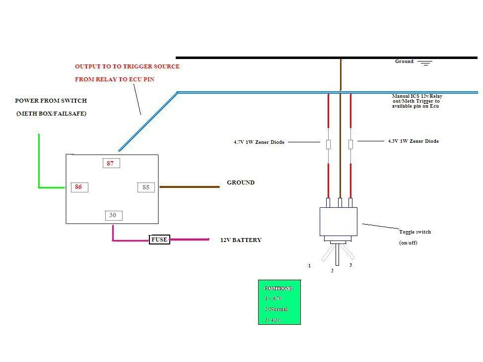
not sure if this will work, throwing it out there..just spent 30mins on this diagram. It's a simple diode with toggle switch. The zener diode will drop the remaining voltage to a ground from the #2 pole. The diode will maintain that the ecu will only see exactly 4.7v. So if your trigger switch from you methbox/failsafe sends 12v/5.1 or whatever the diode will keep it consistent. You have 3 settings on the toggle switch. 1) 4.7v if the ecu sees this it will trigger the map swap. 2) Does nothing and will send 12v/ whatever your trigger emits. 3) 4.3v This will be basically be the off switch so if for some reason you don't want your failsafe/map switching to be part of the equation according to what teph writes if the ecu doesn't see 4.7v then it won't switch, so 4.3v will maintain the same map.
4.7v = map switch
0v = maintain current map
Diagram below. What do you think?
4.7v = map switch
0v = maintain current map
Diagram below. What do you think?
Last edited by Evoryder; Jan 3, 2008 at 10:33 PM.
Jan 3, 2008, 10:38 PM
#208
Umm, the diodes aren't going to drop a 12v source to 4.7 or 4.3 volts. We've found a 5V source on both the 8 and 9 ecu's so all you need is to have the 5v source go to pin 30 on the relay and have pin 87 go straight to the ADC input on the ECU. A diode in series will drop between .1-.7 volts, the way it seems you have it wired doesn't seem to even interupt the wire going from the relay to the ecu? You're saying have it in parallel?
EDIT: the way it works, if it see's no connection to voltage at all it runs the regular map. If it see's 5V it runs the alt map. So all you need to do is interrupt a connection from a 5v source
EDIT: the way it works, if it see's no connection to voltage at all it runs the regular map. If it see's 5V it runs the alt map. So all you need to do is interrupt a connection from a 5v source
Last edited by Jack_of_Trades; Jan 3, 2008 at 10:41 PM.
Jan 3, 2008, 10:54 PM
#209
Umm, the diodes aren't going to drop a 12v source to 4.7 or 4.3 volts. We've found a 5V source on both the 8 and 9 ecu's so all you need is to have the 5v source go to pin 30 on the relay and have pin 87 go straight to the ADC input on the ECU. A diode in series will drop between .1-.7 volts, the way it seems you have it wired doesn't seem to even interupt the wire going from the relay to the ecu? You're saying have it in parallel?
EDIT: the way it works, if it see's no connection to voltage at all it runs the regular map. If it see's 5V it runs the alt map. So all you need to do is interrupt a connection from a 5v source
EDIT: the way it works, if it see's no connection to voltage at all it runs the regular map. If it see's 5V it runs the alt map. So all you need to do is interrupt a connection from a 5v source

Relay,
86- trigger from meth box
30-5v source from pin on ecu(avail. both 8's and 9's)...maintain inline fuse?
87- to ecu pin for switching maps.
30 - ground
Sounds like a plan..can't wait to get this system up and running.
Jan 3, 2008, 11:08 PM
#210
PIN 42 is map switching input (connected to pin 87 on relay)
PIN 52(still confirming it stays on under all conditions) is 5V source (connected to pin 30 on relay)
Evo 9's:
PIN 64 is map switching input (connected to pin 87 on relay)
PIN 23(still confirming it stays on under all conditions) is 5V source (connected to pin 30 on relay)
I don't think a fuse is really necessary on the 5v wire since no current is drawn at ALL, it only reads a difference in voltage potential (like a digital volt meter does). I would however put a 3 or 5 amp inline fuse on the +12V wire that powers up the relay.
Some alky kits might have a +12V trigger, some might have a trigger that is a ground so you'd just need to make sure the opposite side of the relay gets the appropriate connection to power it up.
Once we prove the new ROM coding works and I get my set of ECU pins in the mail, I'll do a full tutorial on how to add this stuff. Its gonna be a REALLY easy and a VERRRY cheap upgrade
Last edited by Jack_of_Trades; Jan 4, 2008 at 11:53 AM.