
Maf Scaling table
 Dec 19, 2006, 08:06 PM
#31
1600hz makes sense simply because the scaling for the MAF HZ MUT value clips at 1609hz.. However the logic for me is the conversion I chose, is what is used by the MUT output for MAF frequency, and therefore made more sense from a "Programmers logic" point of view.
But the scale is a configurable axis, so we need to try to nail it down a bit.
Even though the MAF is generally considered linear, I have found it really isn't depending on your modifications.
But the scale is a configurable axis, so we need to try to nail it down a bit.
Even though the MAF is generally considered linear, I have found it really isn't depending on your modifications.
 Dec 20, 2006, 08:29 AM
#32
Evolved Member
iTrader: (19)
Join Date: Sep 2005
Location: Butthole, MA
Posts: 834
Likes: 0
Received 0 Likes
on
0 Posts
I have been doing this also since I figured out the scaling.. I think the actual scaling starts at around 30hz, as airflow seems inconsistent below that..
The scaling I had been using is the scaling used by MUT, which makes sense.. you don't need a custom scale as the axis does already exist for this..
use x/6.29 and x*6.29 , UINT16 and also Little Endian..
Remember that this axis is a configurable parameter for different MAF sensors and the range should also be able to be modified (I have seen this in a Lancer ROM that of course is a different size and has a different MAF range..
and it correlates almost perfectly with the range of the MAF
Dec 22, 2006, 05:58 PM
#33
Evolved Member
iTrader: (19)
Join Date: Sep 2005
Location: Butthole, MA
Posts: 834
Likes: 0
Received 0 Likes
on
0 Posts
I'm so clueless 
My STFT are up to 25% at some points
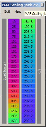
So here is my stock maf scaling table:

And I just thought I'd increase the first few values by 10% to see if my trims could go down some. They didn't.

Fun fun.
My STFT are up to 25% at some points
So here is my stock maf scaling table:
And I just thought I'd increase the first few values by 10% to see if my trims could go down some. They didn't.
Fun fun.
Dec 22, 2006, 06:07 PM
#34

I should be doing some testing this weekend hopefully to see what I can figure out.
Out of curiosity though, when are your STFTs up to +25%...at idle, cruise? When you said they didn't change at all, was this done at idle or cruise? STFT will jump around a lot and it may be hard to notice any change in them. I'm just wondering if what you changed did or didn't actually have an effect.
Also, after reading some more, I think the final airflow calculation in the ECU uses an adder value on top of this compensation map, and then the MAF size as the multiplier. So, basically, changing this number up by 10% would not have a 10% change in fueling calculation, so to speak.
But, like I said, I don't know any of this for sure yet. Hopefully I can test this weekend.
Eric
Last edited by l2r99gst; Dec 22, 2006 at 06:12 PM.
Dec 23, 2006, 07:19 AM
#35
Evolved Member
iTrader: (19)
Join Date: Sep 2005
Location: Butthole, MA
Posts: 834
Likes: 0
Received 0 Likes
on
0 Posts
I should be doing some testing this weekend hopefully to see what I can figure out.
Out of curiosity though, when are your STFTs up to +25%...at idle, cruise? When you said they didn't change at all, was this done at idle or cruise? STFT will jump around a lot and it may be hard to notice any change in them. I'm just wondering if what you changed did or didn't actually have an effect.
Also, after reading some more, I think the final airflow calculation in the ECU uses an adder value on top of this compensation map, and then the MAF size as the multiplier. So, basically, changing this number up by 10% would not have a 10% change in fueling calculation, so to speak.
But, like I said, I don't know any of this for sure yet. Hopefully I can test this weekend.
Eric
Out of curiosity though, when are your STFTs up to +25%...at idle, cruise? When you said they didn't change at all, was this done at idle or cruise? STFT will jump around a lot and it may be hard to notice any change in them. I'm just wondering if what you changed did or didn't actually have an effect.
Also, after reading some more, I think the final airflow calculation in the ECU uses an adder value on top of this compensation map, and then the MAF size as the multiplier. So, basically, changing this number up by 10% would not have a 10% change in fueling calculation, so to speak.
But, like I said, I don't know any of this for sure yet. Hopefully I can test this weekend.
Eric
I made some changes to that MAF scaling table as I had posted pics of.
I went back to my car and didn't see any sort of changes in trims. I expected them to go down.
Dec 23, 2006, 04:43 PM
#37
OK, did some brief testing today to try to get the ratio of my scalings correct first. This way I could get a pretty good equation for mass airflow based on air density and the formula for the graph of L/s vs Hz.
For now, I have added these formulas to LogWorks to calculate air density and mass airflow. I also added a g/rev since I am used to this value from DSMLink. To get the ratio of my scalings correct, I did a third gear pull twice on the same stretch of road, within about 10 minutes of each other. The first pull was logging using the MUT protocol and LogWorks, so that I could log Hz, baro, intake temp, RPM, etc. The second log was with OBD-II, so that I could log mass airflow (g/s) and RPM. That way I could look at both logs to verify the ratio of my scalings in my spreadsheet of L/S vs Hz.
Anyway, to make a long story short, I have added these equations to LogWorks for now:
#Forumla to calculate g/s from airflow.baro.
#and intake temp
airdens=Atmospheric_Pressure /14.6956/.08026/(Intake_Air_Temp +273.15)*28.9
massaircalc=(-7*10^-09*AirFlow^3 + 3*10^-05*AirFlow^2+ 0.1051*AirFlow - 1) *airdens
MC(airdens;g/L) = airdens
MC(massair-calc;g/s) = massaircalc
#Forumla to calculate g/s from airflow.baro.
#and intake temp
airdens=Atmospheric_Pressure /14.6956/.08026/(Intake_Air_Temp +273.15)*28.9
massaircalc=(-7*10^-09*AirFlow^3 + 3*10^-05*AirFlow^2+ 0.1051*AirFlow - 1)*airdens
GperRev=massaircalc*60/Engine_Speed
MC(GperRv;g/rev) = GperRev
I am also going to add a lb/min calculation, which is simply the g/s *60/454. I am used to lb/min also and this correlates well with compressor maps, HP numbers, etc.
Here is my 3rd gear pull from today using LogWorks with these new formulas added. The mass airflow matches pretty well with the OBD-II pull now and so far everything is looking pretty good. Hopefully tomorrow, I can verify the scalings for the Hz and then come up with some finalized equations and perhaps an attempt at an explanation of the maf scaling table.

Actually, my car at the moment just has a 3" TBE with 3" hi-flow cat and EBC (I'm installing cams one of these next few days). The rest is stock, right down to the intake and stock paper filter...evn the tune is pretty much stock, I have barely touched anything yet. Actually, this is a good example of how restrictive the stock filter and/or airbox is. Look at how much the baro drops (darker yellow line towards the top) and the resulting drop in air density (yellow lines dropping from middle of graph towards the bottom - one of the calculated formulas from above).
Eric
For now, I have added these formulas to LogWorks to calculate air density and mass airflow. I also added a g/rev since I am used to this value from DSMLink. To get the ratio of my scalings correct, I did a third gear pull twice on the same stretch of road, within about 10 minutes of each other. The first pull was logging using the MUT protocol and LogWorks, so that I could log Hz, baro, intake temp, RPM, etc. The second log was with OBD-II, so that I could log mass airflow (g/s) and RPM. That way I could look at both logs to verify the ratio of my scalings in my spreadsheet of L/S vs Hz.
Anyway, to make a long story short, I have added these equations to LogWorks for now:
#Forumla to calculate g/s from airflow.baro.
#and intake temp
airdens=Atmospheric_Pressure /14.6956/.08026/(Intake_Air_Temp +273.15)*28.9
massaircalc=(-7*10^-09*AirFlow^3 + 3*10^-05*AirFlow^2+ 0.1051*AirFlow - 1) *airdens
MC(airdens;g/L) = airdens
MC(massair-calc;g/s) = massaircalc
#Forumla to calculate g/s from airflow.baro.
#and intake temp
airdens=Atmospheric_Pressure /14.6956/.08026/(Intake_Air_Temp +273.15)*28.9
massaircalc=(-7*10^-09*AirFlow^3 + 3*10^-05*AirFlow^2+ 0.1051*AirFlow - 1)*airdens
GperRev=massaircalc*60/Engine_Speed
MC(GperRv;g/rev) = GperRev
I am also going to add a lb/min calculation, which is simply the g/s *60/454. I am used to lb/min also and this correlates well with compressor maps, HP numbers, etc.
Here is my 3rd gear pull from today using LogWorks with these new formulas added. The mass airflow matches pretty well with the OBD-II pull now and so far everything is looking pretty good. Hopefully tomorrow, I can verify the scalings for the Hz and then come up with some finalized equations and perhaps an attempt at an explanation of the maf scaling table.
Actually, my car at the moment just has a 3" TBE with 3" hi-flow cat and EBC (I'm installing cams one of these next few days). The rest is stock, right down to the intake and stock paper filter...evn the tune is pretty much stock, I have barely touched anything yet. Actually, this is a good example of how restrictive the stock filter and/or airbox is. Look at how much the baro drops (darker yellow line towards the top) and the resulting drop in air density (yellow lines dropping from middle of graph towards the bottom - one of the calculated formulas from above).
Eric
Last edited by l2r99gst; Dec 23, 2006 at 04:52 PM.
Dec 23, 2006, 07:13 PM
#38
Evolved Member
iTrader: (19)
Join Date: Sep 2005
Location: Butthole, MA
Posts: 834
Likes: 0
Received 0 Likes
on
0 Posts
OK, did some brief testing today to try to get the ratio of my scalings correct first. This way I could get a pretty good equation for mass airflow based on air density and the formula for the graph of L/s vs Hz.
For now, I have added these formulas to LogWorks to calculate air density and mass airflow. I also added a g/rev since I am used to this value from DSMLink. To get the ratio of my scalings correct, I did a third gear pull twice on the same stretch of road, within about 10 minutes of each other. The first pull was logging using the MUT protocol and LogWorks, so that I could log Hz, baro, intake temp, RPM, etc. The second log was with OBD-II, so that I could log mass airflow (g/s) and RPM. That way I could look at both logs to verify the ratio of my scalings in my spreadsheet of L/S vs Hz.
Anyway, to make a long story short, I have added these equations to LogWorks for now:
#Forumla to calculate g/s from airflow.baro.
#and intake temp
airdens=Atmospheric_Pressure /14.6956/.08026/(Intake_Air_Temp +273.15)*28.9
massaircalc=(-7*10^-09*AirFlow^3 + 3*10^-05*AirFlow^2+ 0.1051*AirFlow - 1) *airdens
MC(airdens;g/L) = airdens
MC(massair-calc;g/s) = massaircalc
#Forumla to calculate g/s from airflow.baro.
#and intake temp
airdens=Atmospheric_Pressure /14.6956/.08026/(Intake_Air_Temp +273.15)*28.9
massaircalc=(-7*10^-09*AirFlow^3 + 3*10^-05*AirFlow^2+ 0.1051*AirFlow - 1)*airdens
GperRev=massaircalc*60/Engine_Speed
MC(GperRv;g/rev) = GperRev
I am also going to add a lb/min calculation, which is simply the g/s *60/454. I am used to lb/min also and this correlates well with compressor maps, HP numbers, etc.
Here is my 3rd gear pull from today using LogWorks with these new formulas added. The mass airflow matches pretty well with the OBD-II pull now and so far everything is looking pretty good. Hopefully tomorrow, I can verify the scalings for the Hz and then come up with some finalized equations and perhaps an attempt at an explanation of the maf scaling table.
Actually, my car at the moment just has a 3" TBE with 3" hi-flow cat and EBC (I'm installing cams one of these next few days). The rest is stock, right down to the intake and stock paper filter...evn the tune is pretty much stock, I have barely touched anything yet. Actually, this is a good example of how restrictive the stock filter and/or airbox is. Look at how much the baro drops (darker yellow line towards the top) and the resulting drop in air density (yellow lines dropping from middle of graph towards the bottom - one of the calculated formulas from above).
Eric
It looks like you did a lot of work.
Could I get some cliffnotes. I have no clue what you're talking about. Seriously.
Jan 11, 2007, 05:08 PM
#40
OK, I have a little update. I did a couple of pulls to test what the scaling of the Hz column is and from the brief tests I did, it looked like it was indeed scaled to only 1600 Hz, like someone mentioned. I always though it would be higher, so I posted the question on the DSM-ECU boards today and the responses so far all agree that it is to 1600 Hz.
Well, here is my data to support this. It is not definitive data by any means, but it does show something. One of the reasons why I can't definitively state whether this is correct is because our maf compensation (maf scaling in EcuFlash) has very little wiggle room in the higher Hz ranges. These are 8 bit values, so they can only go to 255 max. We already have numbers that go up to 237.
And, on top of that, from talking to a few more people and reading different threads on the ECU boards, it appears that the Evo uses an adder of 140 decimal (8C hex) to add to this scaling value before it multiplies it with the Hz value to get the volumetric airflow number.
So, what this means is that you don't change the maf scaling table value by 10% to see a 10% change in airflow. You will see a much smaller change. Let me explain:
Our maf scaling table looks like this in decimal:
145
152
165
175
182
187
191
195
198
200
203
206
208
217
222
226
233
236
237
235
232
Supposedly (I am still searching for this or waiting for someone to dissemble) a 140 decimal value is added to this number before being multiplied by the Hz number. So, if we take the first number, which is 145, adding 10% to that number would roughly increase your airflow compensation by 5% (145+140=285, 14.5/185= 5.09% change.
Using a larger number further down the list, changing the 237 value by the same 14.5 decimal, would yield (237+140 = 377, 14.5/377 = 3.85% change. Notice that we only have room to move that value up to a max of 255, so the biggest change we could make by only using this table would be 18/377= 4.78%.
OK, so before I even knew that the scaling was to 1600Hz, I simply changed a few values and compared my wideband readings at certain Hz values from a control run (before the changes) to the readings a few minutes later with the changes. The following pictures show the first test:
Here I changed the 5th and 10th values from 182 and 200, to 217 and 235, respectively. So, we should rougly see a 10% change in airflow and thus a 10% change in fueling at the appropriate Hz value.
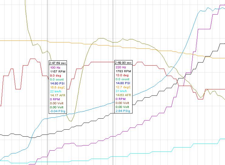

If we assume that the Hz scaling is to 1600 Hz, then this should of changed the fueling at 100hz and 225 Hz, respectively. Well, it turns out that the 100 Hz point is right at the point where I went WOT, not to mention that one one run I came from off throttle coasting down and the next I came from a cruise, so that point has to be thrown out. Looking at the next point, though, we see a nice dip right around 225 Hz, originally at 14.63 afr and now at 13.27, or roughly a 10% change. So, that pans out.
Next, I changed the third value from the bottom from 237 to 254. Unfortunately, this will be much harder to detect, since this change will only be (17/377) 4.5% different. This should be at 1200 Hz. Well, here is that test:
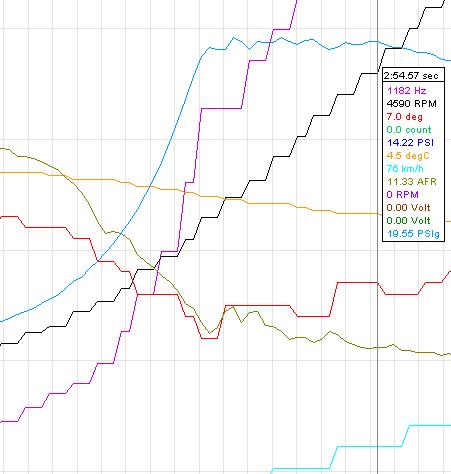
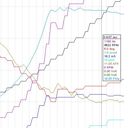
Like I said, this is such a small change, that you can argue that AFRs can change that much from run to run, but if you look at the shape of the curve, they are pretty much identical, except that there is a slight dip, with the trough, or smooth dip down, leading to the 1200Hz value, which is about 2.5% different than the control run. A little under the 4.5% expected, but with the speed of datalogging, variables, etc, this can be expected.
So, take this for what it is worth at this point in time. But, it looks like our Hz values may very well be scaled to 1600 Hz. I asked what does the ECU do after 1600 Hz then, on the DSM-ECU boards, and it was stated that the last compensation (scaling value) is used.
So, now, I guess I have to wait on the dissassembly to see if this 140 adder is correct (which I think it is, because I heard that this came from Thomas Dorris, the creator of DSMLink which dissembled the entire DSM Ecu and wrote additional code/subroutines). But, the other thing that confuses me is our 'maf smoothing table. These values are all very close to 140 decimal and I was thinking maybe the Evo Ecu uses this table as a lookup for the adder instead of using 140, since there is very little room for adjustment in the main compenstaion (scaling) table. If not, then what is this Maf smoothing table for?
Anyway, if someone finds the address of this 8C adder (140 decimal) in their ECU by disassembly, let me know. Maybe jcsbanks can help out on this one?
Thanks,
Eric
Well, here is my data to support this. It is not definitive data by any means, but it does show something. One of the reasons why I can't definitively state whether this is correct is because our maf compensation (maf scaling in EcuFlash) has very little wiggle room in the higher Hz ranges. These are 8 bit values, so they can only go to 255 max. We already have numbers that go up to 237.
And, on top of that, from talking to a few more people and reading different threads on the ECU boards, it appears that the Evo uses an adder of 140 decimal (8C hex) to add to this scaling value before it multiplies it with the Hz value to get the volumetric airflow number.
So, what this means is that you don't change the maf scaling table value by 10% to see a 10% change in airflow. You will see a much smaller change. Let me explain:
Our maf scaling table looks like this in decimal:
145
152
165
175
182
187
191
195
198
200
203
206
208
217
222
226
233
236
237
235
232
Supposedly (I am still searching for this or waiting for someone to dissemble) a 140 decimal value is added to this number before being multiplied by the Hz number. So, if we take the first number, which is 145, adding 10% to that number would roughly increase your airflow compensation by 5% (145+140=285, 14.5/185= 5.09% change.
Using a larger number further down the list, changing the 237 value by the same 14.5 decimal, would yield (237+140 = 377, 14.5/377 = 3.85% change. Notice that we only have room to move that value up to a max of 255, so the biggest change we could make by only using this table would be 18/377= 4.78%.
OK, so before I even knew that the scaling was to 1600Hz, I simply changed a few values and compared my wideband readings at certain Hz values from a control run (before the changes) to the readings a few minutes later with the changes. The following pictures show the first test:
Here I changed the 5th and 10th values from 182 and 200, to 217 and 235, respectively. So, we should rougly see a 10% change in airflow and thus a 10% change in fueling at the appropriate Hz value.
If we assume that the Hz scaling is to 1600 Hz, then this should of changed the fueling at 100hz and 225 Hz, respectively. Well, it turns out that the 100 Hz point is right at the point where I went WOT, not to mention that one one run I came from off throttle coasting down and the next I came from a cruise, so that point has to be thrown out. Looking at the next point, though, we see a nice dip right around 225 Hz, originally at 14.63 afr and now at 13.27, or roughly a 10% change. So, that pans out.
Next, I changed the third value from the bottom from 237 to 254. Unfortunately, this will be much harder to detect, since this change will only be (17/377) 4.5% different. This should be at 1200 Hz. Well, here is that test:
Like I said, this is such a small change, that you can argue that AFRs can change that much from run to run, but if you look at the shape of the curve, they are pretty much identical, except that there is a slight dip, with the trough, or smooth dip down, leading to the 1200Hz value, which is about 2.5% different than the control run. A little under the 4.5% expected, but with the speed of datalogging, variables, etc, this can be expected.
So, take this for what it is worth at this point in time. But, it looks like our Hz values may very well be scaled to 1600 Hz. I asked what does the ECU do after 1600 Hz then, on the DSM-ECU boards, and it was stated that the last compensation (scaling value) is used.
So, now, I guess I have to wait on the dissassembly to see if this 140 adder is correct (which I think it is, because I heard that this came from Thomas Dorris, the creator of DSMLink which dissembled the entire DSM Ecu and wrote additional code/subroutines). But, the other thing that confuses me is our 'maf smoothing table. These values are all very close to 140 decimal and I was thinking maybe the Evo Ecu uses this table as a lookup for the adder instead of using 140, since there is very little room for adjustment in the main compenstaion (scaling) table. If not, then what is this Maf smoothing table for?
Anyway, if someone finds the address of this 8C adder (140 decimal) in their ECU by disassembly, let me know. Maybe jcsbanks can help out on this one?
Thanks,
Eric
Last edited by l2r99gst; Jan 11, 2007 at 05:25 PM.
Jan 11, 2007, 10:17 PM
#41
Eric a question.
So all the maps are scaled off a maximum value of 1600hz? The 1G was what 1606 or something and we are theoretically 1603.95, but what about all the people that have logged higher values? The MAF is still transmitting but the ECU is ignoring? I dont remember alot of my 1G and 2G stuff since I have been away from it for so long.
So all the maps are scaled off a maximum value of 1600hz? The 1G was what 1606 or something and we are theoretically 1603.95, but what about all the people that have logged higher values? The MAF is still transmitting but the ECU is ignoring? I dont remember alot of my 1G and 2G stuff since I have been away from it for so long.
Jan 12, 2007, 05:58 AM
#42
No, the way I understand it is that the Maf scaling table itself is just scaled to 1600 Hz, and anything over 1600 Hz just uses the last value from the Maf scaling table to calculate the volumetric airflow number past 1600 Hz. The ECU still sees and uses numbers well above 1600 Hz. It's just that the scaling, or L/Hz is assumed to be the last value in the table above that point.
Remember, that this table is really a table of Hz vs L/Hz. At different Hz levels you will get different L/Hz values, especially at lower Hz values. That is why there are a lot more compensation points at lower Hz values. Even in the table, as you get further away, towards higher Hz values, there are much larger gaps and the values tend to flatten out.
It is this last value that is then used beyond 1600Hz as the final L/Hz value. This value has 140 added to it, then multiplied by the actual Hz value, which can be well beyond 1600 Hz. Any discrpencies beyond this is handled via the open-loop fuel tables (and possibly a VE table of some sort which we don't have access to).
Eric
Last edited by l2r99gst; Jan 12, 2007 at 06:04 AM.
Jan 12, 2007, 06:20 AM
#43
Yep, that is the same way I have understood it.
What I do find interesting is that looking at the original definitions, the axis is a 16 bit value, and can be "altered", I recall in your earlier posts that you manually entered axis points, this goes against how the ECU generally worked for 2d and 3d values (where every one had an axis lookup.)
So, using the inferrential data that has been gathered, I took the existing definition's axis, and applied a scale if 10.183 to it, and guess what, the first value is about 19hz, and the last value is 1609hz, and the spacing appears to mirror what you also observed.
If this is true, then you now have a configurable axis for HZ and can scale well above the 1609hz value.
Of course, this may not be correct, but it does appear to "Fit" with your observations, while retaining a configurable axis that had been typical of all the existing maps.
Jan 12, 2007, 06:24 AM
#44
This actually makes sense, as from observations I had made without knowing what these tables were, I would see differences in airflow at very low loads and idle, where the amount of air moved (Liter/Hz) would be lower due to the turbo being a restriction at idle, and of course, air being diverted back to the intake at idle would also lower the airflow at very low loads.
I did make an assumption about the values that may not accurate though, and that is the highest value (UINT16) could be 65534, the scale would place the max HZ value at around 6000hz, Its more than likely the scaling is probably half that but we'll have to spend more time looking at the axis itself.
FWIW, If the scale is indeed 10.183, then the raw value is roughly a multiple of 10, so scaling is really not necessary as in my head, 16384 would be 1638.4... This value actually does seem to make sense as its just above the max airflow registered in the MUT protocol, and the MUT protocol suffers from interpolation/clipping error.
So, take this how you want, but I am just making the connection for myself so it makes more sense.
Last edited by MalibuJack; Jan 12, 2007 at 06:37 AM.
Jan 12, 2007, 06:31 AM
#45
Yes, that is how I will be scaling the Hz column in these tables. Either dividing by 10.183 or 10.24 to end exactly at 1600Hz.
For the y data, or maf scaling data, I am using that as simple decimal numbers right now. I am doing this since there is supposedly a 140 decimal adder added to this number, then multiplied by the current Hz number. So, it's easier for me to leave that scale to just decimal values.
But now that leaves me to wonder what the maf smoothing table is and where the hex address for this 140 (8C) adder is. I wish I knew how to read the disassembly. I have IDA Pro and have been looking at the code and the op-code datasheet, but I just don't understand enough to do anything now.
Eric
For the y data, or maf scaling data, I am using that as simple decimal numbers right now. I am doing this since there is supposedly a 140 decimal adder added to this number, then multiplied by the current Hz number. So, it's easier for me to leave that scale to just decimal values.
But now that leaves me to wonder what the maf smoothing table is and where the hex address for this 140 (8C) adder is. I wish I knew how to read the disassembly.
I have IDA Pro and have been looking at the code and the op-code datasheet, but I just don't understand enough to do anything now.Eric