When you click on links to various merchants on this site and make a purchase, this can result in this site earning a commission. Affiliate programs and affiliations include, but are not limited to, the eBay Partner Network.
CT9A Custom tail light design, build project for Evo 9.
So in 2019 I started a project to build LED powered tail lights for my Evo. I started by buying an aftermarket set, and opening them by using an "ultrasonic cutter knife" which vibrates very fast and can make cuts through plastic. Once I had the lenses off (this was not easy) I could start disassembling the lamps and working on my design. One of the challenges was the turn-signals, because there is no easy way to mount a circuit board to hold the LEDs. The stop, parking light, and reverse lights are pretty easy because I could make circle boards that almost press in to fit perfect into the factory locations. The turn signals have a big open area where this isn't really an option. So with 3d cad in Linux I designed a 3d bracket that had many revisions, and I 3d printed it with my 3d printer, in ABS material.
I also had the trim pieces off, so I painted them in my paintbooth with the factory OEM mitsubishi color (my car is a grey MR, and I have paint left over from painting my jdm bumper, and I also had clear coat too).
I also use oven cleaner to remove the chrome inside, so they just look black afterwards.
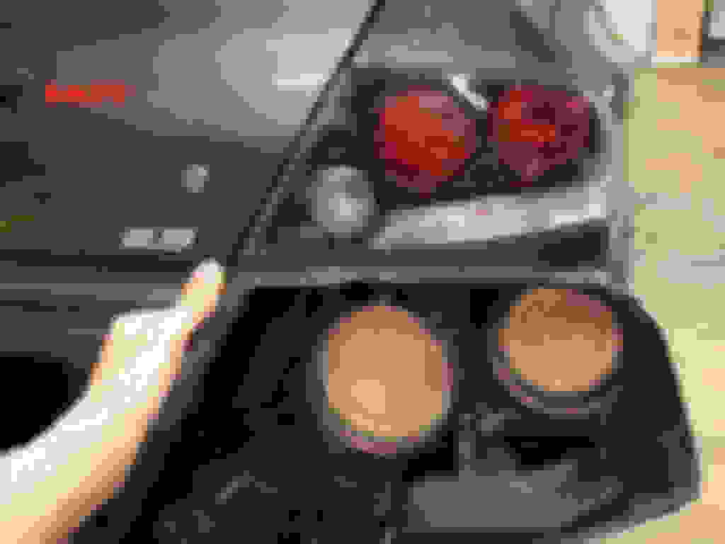
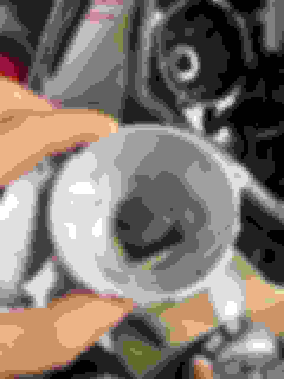
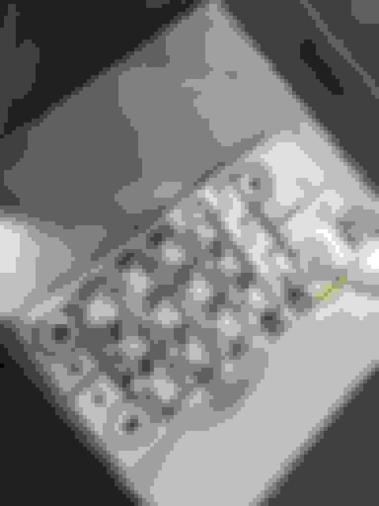
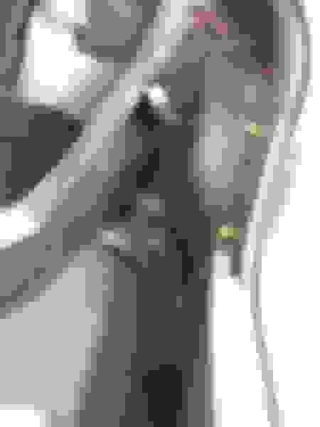
Here you can see the diffuser which I removed, for the original tail light turnsignal bulb. here is the lamp without the diffuser
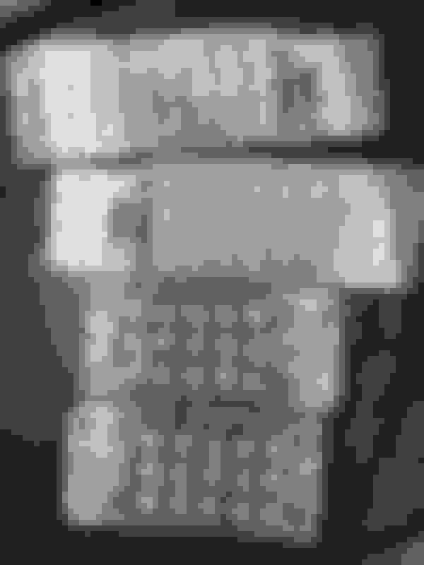
Here you can see my design of the bracket which screws into the original turn signal diffuser location.
I ran into problems getting it to fit with the trim installed, I had to make adjustments this was the first design.... the first design had a flat 'bridge" across the top, this didn't work to well. I had to make the raising part at an angle.
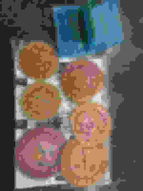
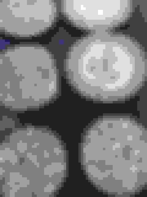
here are some of the circle board design photos
Here you can see the circuitboards made from paper, just testing things out
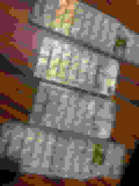
Once I had a bracket that would work, I made my circuit boards. There were a total of 10 boards for the lamps (5 per side) and I had to make 2 "modules" to provide regulated power to the LEDs. I also "tinned" the boards, so they will hold up better. That's why they look silver instead of copper.
Here I am transfering the print to copper so I can etch it with a solution the transfer came out fantastic, this will be a good etch I always print a few incase I have problems the boards after drilling the holes and tinning boards and brackets boards and brackets boards and brackets the boards after drilling the holes and tinning
Here you can see i was test fitting my "circle" style boards before I tinned them. Here I am with my drill bits, this was many holes I had to drill Just comparing. Here you can see the circle boards boards before tinning all the boards with tinning complete, ready for component soldering.
One thing I was not sure on, was finalizing the color of everything before I committed to my plans. I decided to paint the surface of the boards black so they would look like the plastic on the bottom (how it was behind the chrome) The bezels were painted grey to match the Mitsubishi exterior paint. I also had to do the "cups" for the reverse lights- they are silvery from the factory.
scuffing the cup and preparing it for paint base coat sprayed on clear coat sprayed on
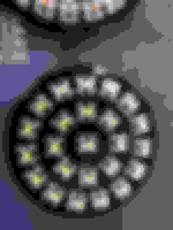
Here is what things look liked after soldering was complete. This was 14 hours of soldering over 2 straight days.
testing things just for a sanity check
I 3d printed little plugs to install into the spots where the bulb sockets go...
I put conformal coating on the boards to protect them. I also glued in the circle boards and mounted the turn-signals. I attached all of the wires and ran them out the back. without bezel installed with bezel installed testing the turn signals here i just set the lenses on to get a look
I had to make a wiring harness that would connect to the oem wiring
Now I had to make power-supplies that would condition the power and regulate it for supply to the tail lights. I made a circuit board with some remotely mounted vRegs so I could do this. I also fed he running lights (which operate at 10v) to the brake lights (which operate at 12v) so the running lights will come on full brightness with the brake lights.. I also made some aluminum boxes and mounts for these so they are hidden in behind the trunk area carpet. I made jumper connectors to the factory wiring and built a plug and play setup so I can swap back to stock at any time.
here you can see this mess of speghetti before I built the connector ends and finished the harness the boxes area aluminum so they help draw heat out of the vregs test fitting the boxes in an corner of the trunk completely hidden plug and play installation here are the power supply modules after they are just about done power supplies vregs mounted
I re-attached the lenses (this was HAIRY). I used an epoxy 2 part urethane glue, similar to what keeps your windshield in. I looked at them, and I decided to mask off the edges so you cant see the spots where they were welded together from the factory (i actually cut behind this area, so you can't see my cut) I then painted this to match the body.
I used this 3m masking tape which is the blue stuff- its very thin and it sticks excellent!
Time for reinstallation to the car.
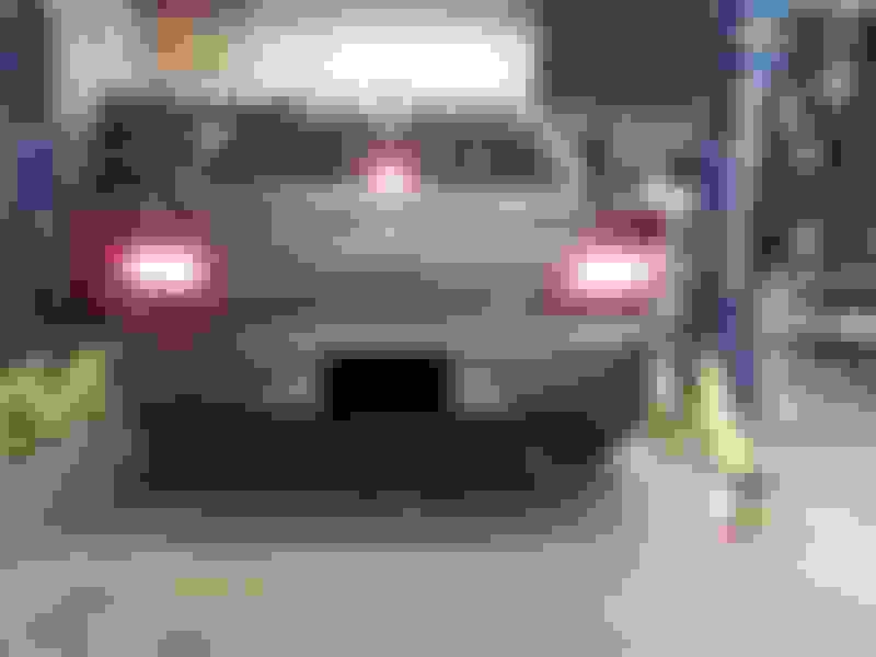
I drove it twice and they seem to function perfect electrically. I have not noticed any problems so far. Here are the running lights and brake lights. It is better to get a picture outside during the day. The LEDs look too washed out with light in my shop with my cell phone camera.
What the crap! That's amazing!!! What did you use to produce the boards for your LED's? Does your 3D printer have that capability? Seriously cool.
I design the boards first with paper (card-stock) and then when i am happy I print with a laser printer, onto this stuff called "Press and peel blue". With this, you have to mirror-image the print out. I turn the print out over, and press it against "copper clad" with a fiberglass backing. I clamp it in a sandwich between 2 pieces of aluminum and put it in the oven for 20 minutes at about 360F. When that is done, the laser toner material melts onto the copper clad. This allows me to dip it in 3 parts hydrogen peroxide and 1 part muriatic acid solution. This eats away the exposed copper where the "press n peel" blue did not transfer any toner to. Once the chemical is done removing the bare copper, I go to town with my band saw.
There are plenty of videos on youtube on making your own PCBs. I am no expert. I have autism (aspergers) so I have no people skills but I can hyper focus on things like this.
That looks awesome! I'm definitely a fan of LED lighting. Looks amazing when done correctly! On a job like this, what would you charge a Joe Smhoe?
I don't know- I'm so loaded with work now that I don't have time. I'm building an LED gauge cluster for a Honda now. I do have a 3rd brake light that I am selling if you're looking for a good LED product: https://www.evolutionm.net/forums/ma...ght-chmsl.html
Don't be mistaken, I don't just do LED work. I work on anything. I have a full shop with a paint booth, hoist, tig welding area and a detail/wash bay.
I'm a sucker for LED rings as tailight running lights. Big fan of yours! great work man
Thanks- Even know I've been making PCBs like this for 10+ years now I love the fact that if you can draw it in CAD you can make a circuit board of it. Seems to never get old for me.
 Oct 19, 2019, 11:47 AM