
how to plumb boost control 101
 Feb 1, 2009, 07:16 PM
#16
To me a MBC is an archaic device to control boost. The pressure you set in one gear might not be the same pressure in other gears, and I've personally seen it in action on other Evo's where the pressure might be set for 23psi in third but spike up to 28-29 in fifth depending on load, or the reverse of that would be 23psi in fifth and only 15 in 1st or 2nd gear. A load-based EBC or manipulation of the stock tables is a much better way IMO and has more control.
 Feb 1, 2009, 10:04 PM
#17

Attachment 128757
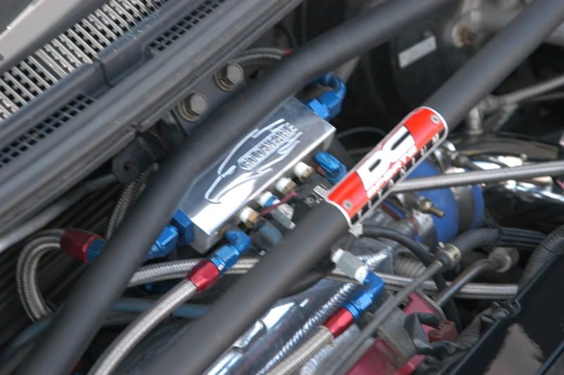
This is from the Blitz boost controller manual with an external WG. The "IN" and "OUT" references are on the boost control solenoid as provided from Blitz.
Josh

This is from the Blitz boost controller manual with an external WG. The "IN" and "OUT" references are on the boost control solenoid as provided from Blitz.
Josh
To me a MBC is an archaic device to control boost. The pressure you set in one gear might not be the same pressure in other gears, and I've personally seen it in action on other Evo's where the pressure might be set for 23psi in third but spike up to 28-29 in fifth depending on load, or the reverse of that would be 23psi in fifth and only 15 in 1st or 2nd gear. A load-based EBC or manipulation of the stock tables is a much better way IMO and has more control.
Feb 1, 2009, 11:16 PM
#18

https://www.evolutionm.net/forums/ev...procedure.html
What 94AWDcoupe is saying is that you should get your boost reference source "directly from boost out at compressor cover or dedicated line from manifold. DO NOT SHARE LINE WITH BOV!" In other words use option #1 below, or a dedicated line from the intake manifold.
Boost Reference Source:
There are two popular choices for the boost reference source for a MBC. I chose to use the second method, there are pro’s and cons to either method.
1. Compressor/Turbo housing discharge nipple
2. "T" into the hose that runs between the diverter valve (DV) & the intake manifold. Note that the DV is often referred to as a BOV.
While "T"ing into the DV/BOV line (Option #2) works well for me, some prefer to get the boost reference source for the turbo discharge nipple.
Dan (drb)
Feb 2, 2009, 05:37 AM
#19
I have been preaching this idea pf individual boost reference to people in my area, for years, and none of them seem to think that it is significant.
This was a reason why I went to a Vaccum Block, with large lines going to it.
Good write up and I glad that someone finally took the time to post this up.
However I want to point this out, I have experienced boost issues when running the source to the boost controller of the compressor housing. What I think happens ( in my case GT35R) the rate at which the boost comes on, can NOT be kept up by the boost controller, which caused a spike in pressure.
When I switched the source to the Intake Manifold, the boost was more controlled. For reference, I am using an EO1 boost controller and this was my solution
In the picture above the vacuum block is feed with two 3/8 in lines. and each device that requires boost, has its own port, so that the boost reference source for everything is the same.
Last edited by antilag_200; Feb 2, 2009 at 05:43 AM.
Feb 2, 2009, 07:14 AM
#22
^ Well I don't want to turn this thread into a vacuum block debate, but here are my thoughts on it
An intake manifold can really be considered a "vacuum block" if you had 12 ports on the back your intake manifold, there wouldn't be the need for a vacuum block.
The way I view it is, I am just creating another small manifold by feeding it with large amounts of air ( now IMO two -6 an lines, is plenty of volume to feed the block). all the sensors that are on the vacuum block should theoretically be at the same datum( amount of vacuum that they draw from the block). Which should then give a more consistant signal to whatever it is that you are trying to read or reference).
Hope that answers your question.
Feb 2, 2009, 07:50 AM
#23
What about WGA plumbed to the atmosphere with a solenoid inline with pressure available by the methanol flow controller as failsafe for <15 psi. For normal ops, the backpressure opens the WG vs spring allowing about 28 peak/23 redline for stock turbo, varies depending on pressure in turbine housing (about 40 psi max). Also the divertervalve has an added port below the diaghram solenoid commanded by the TPS at 4 volts. Stock boost taper for normal commute, locked out at WOT. The DV also is overridden at a knock threashold to dump the charge <20psi
Last edited by C6C6CH3vo; Feb 2, 2009 at 08:01 AM.

Thread
Thread Starter
Forum
Replies
Last Post
Ted B
Evo How To Requests / Questions / Tips
147
Nov 6, 2023 05:38 PM
KingTal0n
Evo Engine / Turbo / Drivetrain
2
Nov 27, 2016 05:23 PM