
intake manifold design questions
 Sep 7, 2011, 07:54 PM
#1

intake manifold design questions
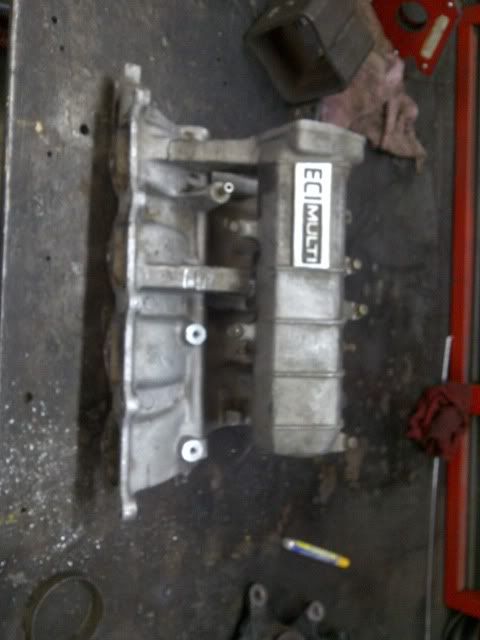
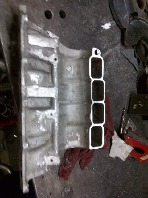
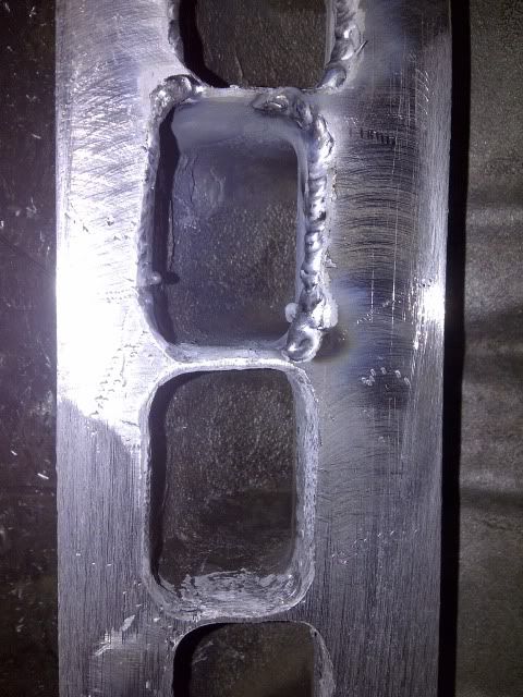
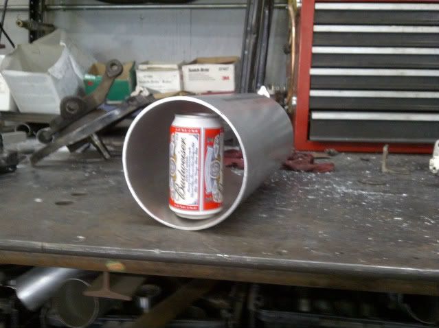
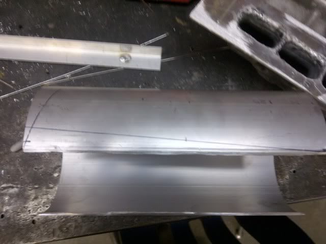
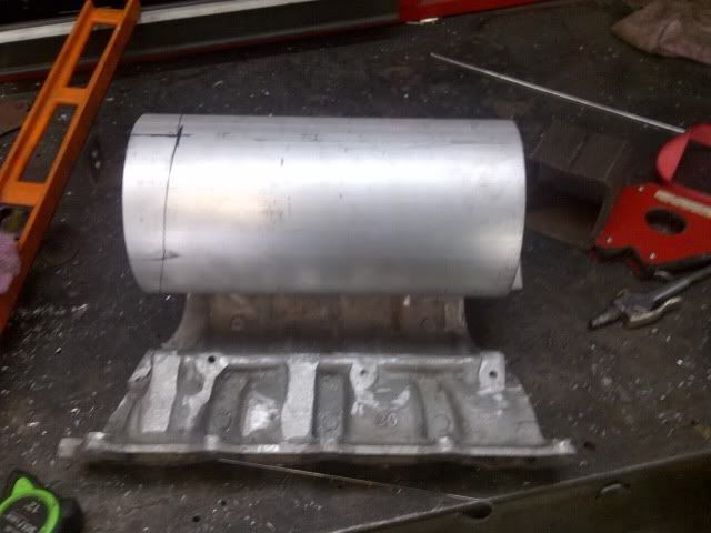
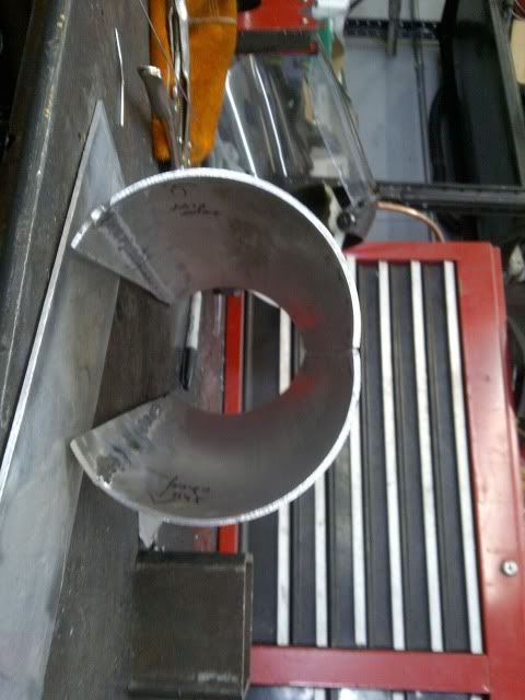
So I have a few questions on intake manifold design. First, the car is an IS300 with a 4g63, so an off the shelf manifold will not work. I took an oem 1g eclipse manifold (due to larger runners). Then I cut off the plenum, and made a 13" x 3" plate and cut out the ports and am welding it to the runners. Then I have some 6" od aluminum that I am planning to cut out 3" length wise, and weld it into the plate. The runners are 8.5" long, and overall plenum volume should be around 300 cubic inches based on the inner diameter and overall length.
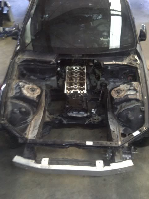
The questions I have are: how much taper should there be in the plenum, and how should I make the endplate shaped (flat, angled, or make it come to a point)? I know this will not be perfect due to not having a flowbench to test it, but I am wanting to make it as good as I can. This is my first manifold I am making, so I am not so sure about those designs. As far as stuff in the engine bay, it is very open, so there is nothing around that area.
Here are the pics

 Sep 8, 2011, 02:49 PM
#4
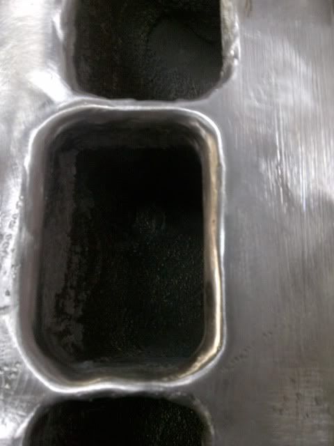
work on your velocity stack area... you're going to need a SERIOUS amount of radius on those inlets.
This means a LOT of welding prior to putting the plenum on.
Runner length is too long IMO. Curved runners = Fail.
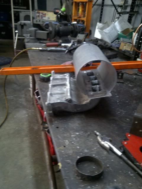
You might want to taper the plenum from the 1st runner to the last as well. I can show you later.
This means a LOT of welding prior to putting the plenum on.
Runner length is too long IMO. Curved runners = Fail.
You might want to taper the plenum from the 1st runner to the last as well. I can show you later.
Sep 8, 2011, 05:26 PM
#5
work on your velocity stack area... you're going to need a SERIOUS amount of radius on those inlets.
This means a LOT of welding prior to putting the plenum on.
Runner length is too long IMO. Curved runners = Fail.
You might want to taper the plenum from the 1st runner to the last as well. I can show you later.
This means a LOT of welding prior to putting the plenum on.
Runner length is too long IMO. Curved runners = Fail.
You might want to taper the plenum from the 1st runner to the last as well. I can show you later.

Trending Topics
Sep 10, 2011, 11:55 AM
#9
How much of a differance do you think the radius I have vs making it 4 times larger will be? If I have to add a lot of material on the backside, I will have to cut the manifold to get the welder in there. On the inside edges, I can only weld them throgh the top.
Sep 16, 2011, 05:39 AM
#12
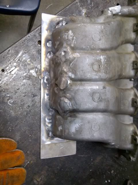
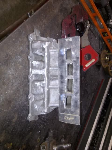
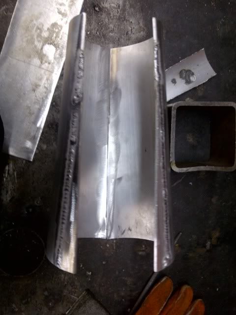
So I made the runner to plenum radius as large as I could without a ton more welding and grinding. I will take pics of that later.
I started modifying the plenum to have cyl. 4 smaller than cyl. 1. I welded the parts I removed onto the bottom, but just tacked everything else. I will take some measurements to see if I want to stick with thos idea.
I started modifying the plenum to have cyl. 4 smaller than cyl. 1. I welded the parts I removed onto the bottom, but just tacked everything else. I will take some measurements to see if I want to stick with thos idea.
Sep 16, 2011, 09:29 AM
#13
Ported Evo manifold + ported 2G head...
That's the direction I would go on that setup.
The 1G runners have virtually no taper to them, so the length with the bend in there is going to hurt power. I'm generally a fan of longer runners, but only if they are fairly straight on path and tapered on the cross-section.
That's the direction I would go on that setup.
The 1G runners have virtually no taper to them, so the length with the bend in there is going to hurt power. I'm generally a fan of longer runners, but only if they are fairly straight on path and tapered on the cross-section.
Last edited by 03whitegsr; Sep 16, 2011 at 09:31 AM.
Sep 16, 2011, 07:45 PM
#14
The evo flange is wrong, so I would have to cut off a dsm flange, and weld it to the evo manifold.
Ported Evo manifold + ported 2G head...
That's the direction I would go on that setup.
The 1G runners have virtually no taper to them, so the length with the bend in there is going to hurt power. I'm generally a fan of longer runners, but only if they are fairly straight on path and tapered on the cross-section.
That's the direction I would go on that setup.
The 1G runners have virtually no taper to them, so the length with the bend in there is going to hurt power. I'm generally a fan of longer runners, but only if they are fairly straight on path and tapered on the cross-section.