When you click on links to various merchants on this site and make a purchase, this can result in this site earning a commission. Affiliate programs and affiliations include, but are not limited to, the eBay Partner Network.
So i went to wire this up today and discovered that things where not what they may have seemed, at least to me. When i tested the stock circuit it wasn't behaving like i expected, it seemed to be energizing the coil all the time. This couldn't be right i was thinking, perhaps i had tapped the wrong wire. I quadruple checked the diagrams and the pinouts and everything was right. Then i realized my mistake, after a closer look at the wiring diagram I found that the bypass relay is normally closed! This means the ECU energizes the coil to open the relay and force current through the resistor. This is the opposite behavior I had expected. Maybe your thinking just wire the bypass relay to be normally closed too, but the problem with that is the bypass relay is wired straight to the battery, which means if its normally closed then the fuel pump will get power all the time when the car isn't running. The simple and obvious thing to do is just add another relay to invert this behavior, but I'm gonna try see if there is something else I can do first. I'm open to suggestions if anyone has any.
Yes, for Evo 8/9, the low/full voltae relay (relay #3) is normally closed (as indicated in the diagrams I posted), however for Evo 10, Mitsu got rid of one relay, and changed the low/full voltage relay to normally open. I wasn't paying attention and thought you were applying this to your Evo 10, so I didn't comment.
Yes, for Evo 8/9, the low/full voltae relay (relay #3) is normally closed (as indicated in the diagrams I posted), however for Evo 10, Mitsu got rid of one relay, and changed the low/full voltage relay to normally open. I wasn't paying attention and thought you were applying this to your Evo 10, so I didn't comment.
Yah i looked at the diagrams a million times and it just went right over my head. Evo X should work no problem, and ill get to that one next.
Yes, for Evo 8/9, the low/full voltae relay (relay #3) is normally closed (as indicated in the diagrams I posted), however for Evo 10, Mitsu got rid of one relay, and changed the low/full voltage relay to normally open. I wasn't paying attention and thought you were applying this to your Evo 10, so I didn't comment.
As a follow-up, could you verify that you have the correct transistor relay? I blew one of the fuel pump transitor relays in my ECU, and it was different (smaller and fewer pins) than the one you show. I think you traced it correctly on the board, but curious about whether you got the correct pin. Have you checked what pin is attached to the other two connections on the powerside of the transistor? That pin should connect to ground.
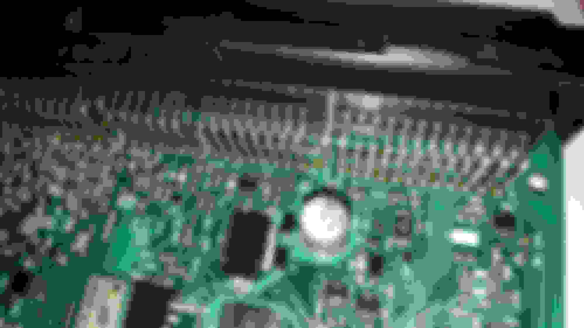
The pin i started from and traced back is correct(pin 39), checked it many times. That pin then traces back into pins 6 & 5 of the transistor, which are both drain 2. The 2 pins to the left of those are pins 7 & 8 which are drain 1. Pins 1 & 3 on the bottom of the chip are Source 1 and source 2. It looks like source 1 goes into a grounding plane, and source 2 i cannot really tell from the photos. I have already put the ECU back into the car though so I can't really test it further. I do recall tracing out the pin leading to drain 1 and it was something to do with AC but I didn't write it down so im not 100% on that.
As a side note i did have pin 39 trigger my bypass relay and it had no problem doing it, but yah the circuit needs some revision to work as intended.
Here is an album i threw together of all the pictures i took of the ECU. Many are of the same area just from different angles. http://imgur.com/a/LRxhb
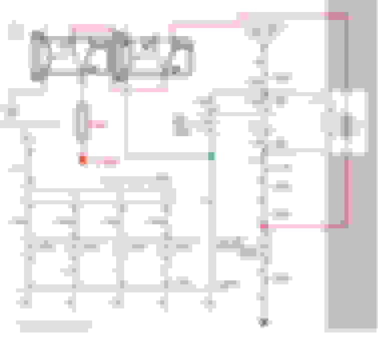
To follow that up here is an image, circled in red is the only 16 pin connector on the ecu C-119 and in pink is pin 39.
Last edited by Biggiesacks; Sep 14, 2016 at 01:13 PM.
Actually looking over my pictures the other side of that transistor seems to go to pin 11 of C-121 which I think is the turbocharger wastegate solenoid.
The one I blew looks like that, but can't say if its the exact same one as you show because the Evo 9 ECU board and components are somewhat different. I believe I blew the transistor relay for fuel pump relay #2. I've kinda forgotten.
The one I blew looks like that, but can't say if its the exact same one as you show because the Evo 9 ECU board and components are somewhat different. I believe I blew the transistor relay for fuel pump relay #2. I've kinda forgotten.
I used the pictures i have to trace Relay 2 (Pin 22 C-121), to that transistor on my board. Unfortunately there isn't much to go off from the picture to try and find a data sheet. I'll avoid adding any additional current to that circuit though.
I got a little distracted by work, but I have finished wiring this up. I went with 2 relays wired in the following way:
After studying this diagram you might be thinking, ok but what if the car is shut off during high voltage mode, ie crank to no start etc. Well the behavior of the stock control circuit is to rest at ground, even if the car is shut off. Its because of this that even if you shut the car off with the high voltage circuit active it will still pull relay 2 to normally open and prevent the infinite loop. This is tested and working on my evo 8.
I ran into a weird issue yesterday, my circuit exhibited the signs of a blown relay. OK, so I switched out the relay...weird, still running the pump after key off. Switched for a third relay, still running. I thought to myself there is no way that three relays could all be bad, so I let the car cool down in the garage (it was in the 90s yesterday).
2 hours later, tested it with the original relay. No issues with that relay or any of the other three. I really don't know where the gremlin lies in the system that is triggered by high heat.
I was wrong, it seems the circuit holds the condition it was last in when the car is shut off. So if its at ground when you shut it off it stays at ground. If its activating the high voltage circuit then it stays that way. That being said I might just wire relay 1( The left relay I added in my diagram) to a 12v switched source and call it a day.
Last edited by Biggiesacks; Sep 23, 2016 at 11:13 AM.
I was wrong, it seems the circuit holds the condition it was last in when the car is shut off. So if its at ground when you shut it off it stays at ground. If its activating the high voltage circuit then it stays that way. That being said I might just wire relay 1 to a 12v switched source and call it a day.
This is why I am suggesting to everyone to simply go with a pressure switch. It avoids all this goofing around.
This is why I am suggesting to everyone to simply go with a pressure switch. It avoids all this goofing around.
I agree that is the easiest hassle free way of doing it, and I would not advocate otherwise at this point. Goofing around is how i get my kicks though, i have to assume your kind of the same in that regard considering how much you tinker with the factory code.
I agree that is the easiest hassle free way of doing it, and I would not advocate otherwise at this point. Goofing around is how i get my kicks though, i have to assume your kind of the same in that regard considering how much you tinker with the factory code.

 Sep 14, 2016, 12:16 PM