1.25" vs 1.5" exhaust manifold comparsion test
 Jan 4, 2015, 10:06 PM
#16
Evolving Member
Thread Starter
Join Date: Jan 2014
Location: Australia
Posts: 440
Likes: 0
Received 0 Likes
on
0 Posts
also another design that is popular now is the contoured flange.
My own comparison: https://www.evolutionm.net/forums/ve...-toxicfab.html
Cliff notes is that they were very close to the same on the dyno, but the 1.5" manifold had better daily driving manners. Issue with the 1.25" primaries was that it felt a bit like it was being choked during off boost daily driving. It was nothing I could capture in a data log. Just seat of the pants difference in responsiveness.
Cliff notes is that they were very close to the same on the dyno, but the 1.5" manifold had better daily driving manners. Issue with the 1.25" primaries was that it felt a bit like it was being choked during off boost daily driving. It was nothing I could capture in a data log. Just seat of the pants difference in responsiveness.
All else being equal, the primary diameter that preserves the maximum exhaust gas velocity without causing a significant backpressure penalty at peak mass airflow (peak hp) generates the quickest spool characteristics and most power under the curve. I emphasized all else being equal because exhaust backpressure represents an average reading that doesn't tell us the complete picture where primary gas velocity and pulse reflection are concerned, especially on an individual cylinder basis. Any disruption along the flow path (especially the tubing walls) tends to create some degree of pulse reflection, which results in an instantaneous pressure wave in the opposite direction. Where the engine speed results in the reflected wave returning to the exhaust valve at the same instant that valve opens, VE is reduced at that rpm. This is disadvantageous in a turbo engine, just as it is an NA engine, and is one big reason why a good FF manifold presents the potential for better power. One advantageous design feature mentioned by 'John Bradley' (above) is a length of straight tubing at the exhaust port exit, before the first bend. Better designs employ at least 4" (100mm) before the first bend. This feature of manifold design reduces the effect of a significant source of pulse reflection.
IF the primary orifice is smaller than the exhaust port as you mentioned the case with one of the manifolds you tested, that is a source of velocity-reducing turbulence and pulse reflection, which again, accounts for the all else being equal caveat. Efficient designs often feature a low angle adjustment from the port orifice into the closest tubing size, but that isn't something we can expect to see in an OE fitment exhaust manifold.
IF the primary orifice is smaller than the exhaust port as you mentioned the case with one of the manifolds you tested, that is a source of velocity-reducing turbulence and pulse reflection, which again, accounts for the all else being equal caveat. Efficient designs often feature a low angle adjustment from the port orifice into the closest tubing size, but that isn't something we can expect to see in an OE fitment exhaust manifold.
cheers
 Jan 4, 2015, 10:24 PM
#17
Evolving Member
Thread Starter
Join Date: Jan 2014
Location: Australia
Posts: 440
Likes: 0
Received 0 Likes
on
0 Posts
All else being equal, the primary diameter that preserves the maximum exhaust gas velocity without causing a significant backpressure penalty at peak mass airflow (peak hp) generates the quickest spool characteristics and most power under the curve. I emphasized all else being equal because exhaust backpressure represents an average reading that doesn't tell us the complete picture where primary gas velocity and pulse reflection are concerned, especially on an individual cylinder basis. Any disruption along the flow path (especially the tubing walls) tends to create some degree of pulse reflection, which results in an instantaneous pressure wave in the opposite direction. Where the engine speed results in the reflected wave returning to the exhaust valve at the same instant that valve opens, VE is reduced at that rpm. This is disadvantageous in a turbo engine, just as it is an NA engine, and is one big reason why a good FF manifold presents the potential for better power. One advantageous design feature mentioned by 'John Bradley' (above) is a length of straight tubing at the exhaust port exit, before the first bend. Better designs employ at least 4" (100mm) before the first bend. This feature of manifold design reduces the effect of a significant source of pulse reflection.
IF the primary orifice is smaller than the exhaust port as you mentioned the case with one of the manifolds you tested, that is a source of velocity-reducing turbulence and pulse reflection, which again, accounts for the all else being equal caveat. Efficient designs often feature a low angle adjustment from the port orifice into the closest tubing size, but that isn't something we can expect to see in an OE fitment exhaust manifold.
IF the primary orifice is smaller than the exhaust port as you mentioned the case with one of the manifolds you tested, that is a source of velocity-reducing turbulence and pulse reflection, which again, accounts for the all else being equal caveat. Efficient designs often feature a low angle adjustment from the port orifice into the closest tubing size, but that isn't something we can expect to see in an OE fitment exhaust manifold.
The two key aspects that I see in header design are flow resistance and how well the collector lines up with the volutes in the hotside.
Here are my thoughts on factors affecting flow resistance.
1) Tubing diameter.
2) Number of bends.
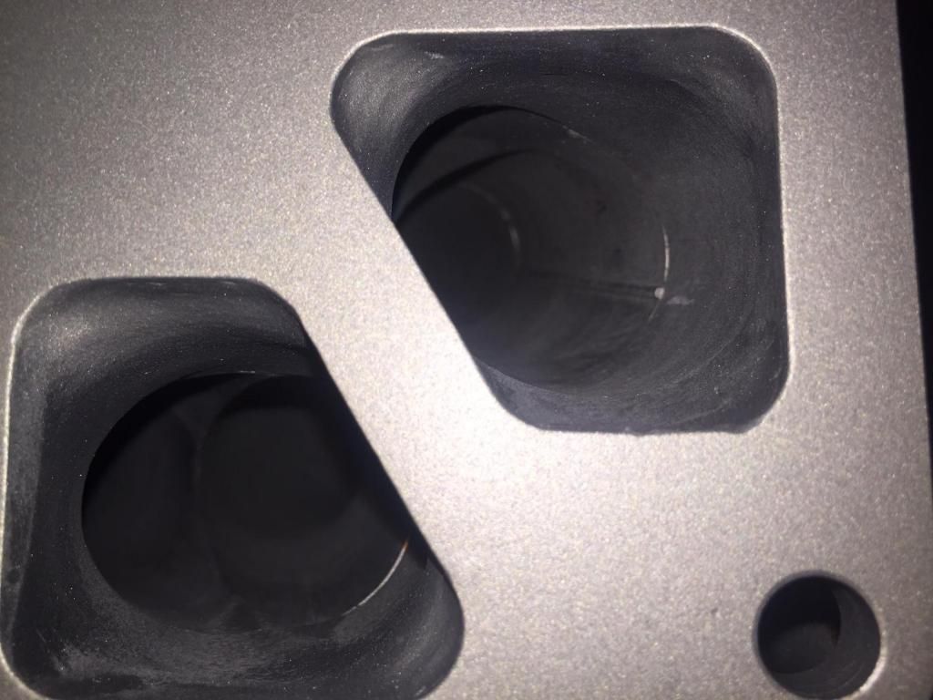
3) The tubing transition where the manifold bolts to the head. The exhaust ports on the head are much larger in cross section than the ID of the 1.25" tubing header. I've not been impressed with most of the transitions I've seen on small diameter headers. Its typically a 45 deg cone reducer that takes place over the thickness of the header flange (1/2" at the most). This was the case for the FiD manifold. The ToxicFab I tried had the same transition method, but since it was 1.5" tubing, it was a more gentle transition. My personal opinion is that this transition is very important. I think a poor transition could be worth 10 bends. The good news is that many of the newer manifolds out there (ToxicFab V3, MAP) use a much smoother transition.
I think the bottom line though is that these aspects of header design have a relatively small effect on exhaust back pressure, probably in the range of 0-5 psi depending on exhaust flow rate. This would be important for a naturally aspirated motor, but for a turbo motor where exhaust manifold back pressure quickly rises above 10 psi under boost and typically matches the boost pressure at peak power (20+ psi for many Evo owners and probably 40+ psi for most stock turbo owners running E85), header design perhaps comes into play predominantly for people who are running relatively tame boost levels.
As far as the collector goes, a well aimed collector will efficiently shoot the exhaust pulses down the volute. A smaller diameter tubing at the collector will also result in a higher velocity pulse shooting down the volute. I think the FiD won here because of the smaller diameter tubing, the collector angle was tighter (better aiming), and it was pointed more accurately down the volutes.
I've love to see a header similar to what Aaron suggested - 1.5" primaries with a well-aimed 1.25" tubing collector. If there were room in the engine bay, I'd actually merge the tubing pairs before the turbo so that a single tube could be pointed down each volute for the most accurate targeting down the volutes. If only I knew how to weld, I could come up with the craziest stuff.
Here are my thoughts on factors affecting flow resistance.
1) Tubing diameter.
2) Number of bends.
3) The tubing transition where the manifold bolts to the head. The exhaust ports on the head are much larger in cross section than the ID of the 1.25" tubing header. I've not been impressed with most of the transitions I've seen on small diameter headers. Its typically a 45 deg cone reducer that takes place over the thickness of the header flange (1/2" at the most). This was the case for the FiD manifold. The ToxicFab I tried had the same transition method, but since it was 1.5" tubing, it was a more gentle transition. My personal opinion is that this transition is very important. I think a poor transition could be worth 10 bends. The good news is that many of the newer manifolds out there (ToxicFab V3, MAP) use a much smoother transition.
I think the bottom line though is that these aspects of header design have a relatively small effect on exhaust back pressure, probably in the range of 0-5 psi depending on exhaust flow rate. This would be important for a naturally aspirated motor, but for a turbo motor where exhaust manifold back pressure quickly rises above 10 psi under boost and typically matches the boost pressure at peak power (20+ psi for many Evo owners and probably 40+ psi for most stock turbo owners running E85), header design perhaps comes into play predominantly for people who are running relatively tame boost levels.
As far as the collector goes, a well aimed collector will efficiently shoot the exhaust pulses down the volute. A smaller diameter tubing at the collector will also result in a higher velocity pulse shooting down the volute. I think the FiD won here because of the smaller diameter tubing, the collector angle was tighter (better aiming), and it was pointed more accurately down the volutes.
I've love to see a header similar to what Aaron suggested - 1.5" primaries with a well-aimed 1.25" tubing collector. If there were room in the engine bay, I'd actually merge the tubing pairs before the turbo so that a single tube could be pointed down each volute for the most accurate targeting down the volutes. If only I knew how to weld, I could come up with the craziest stuff.
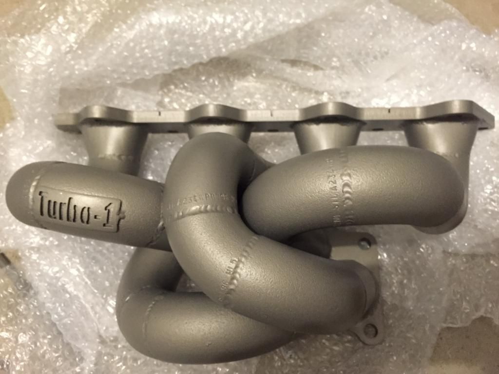
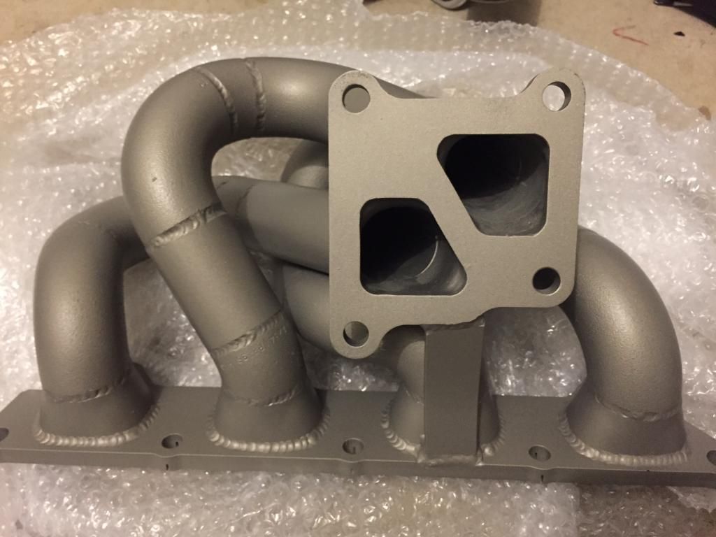
The main reason i was curious about the manifold, was that i had purchased a custom made manifold (not off the shelf).
The size of the manifold is obviously 1.25". I have not yet installed it yet as i will be getting a tuner to install that with a larger turbo, so i don't have to drive it untuned.
The new turbo that will be installed is the; FP BB BLACK.
The new camshafts will be; Power division GSC S2
and the EVO IX will be tuned on E85.
a few people have mentioned to me that for an FPblack� the 1.25" will not be suffice.
what are your thoughts with that comment?
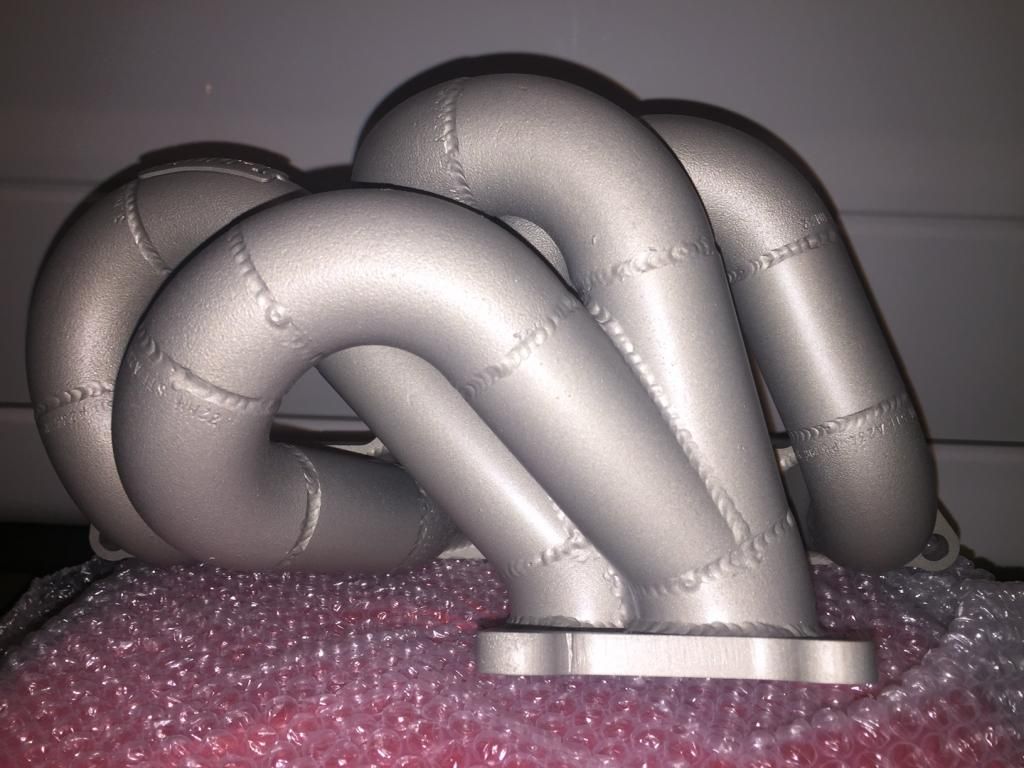
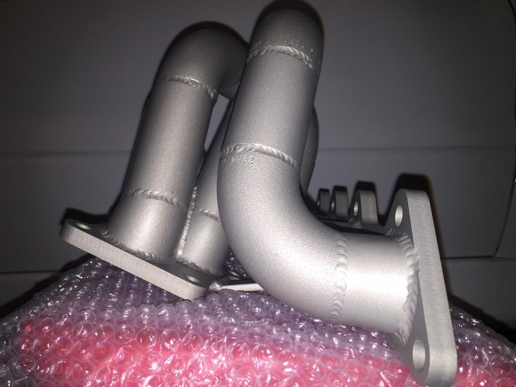
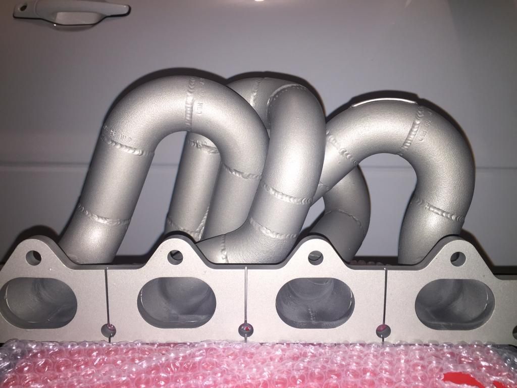
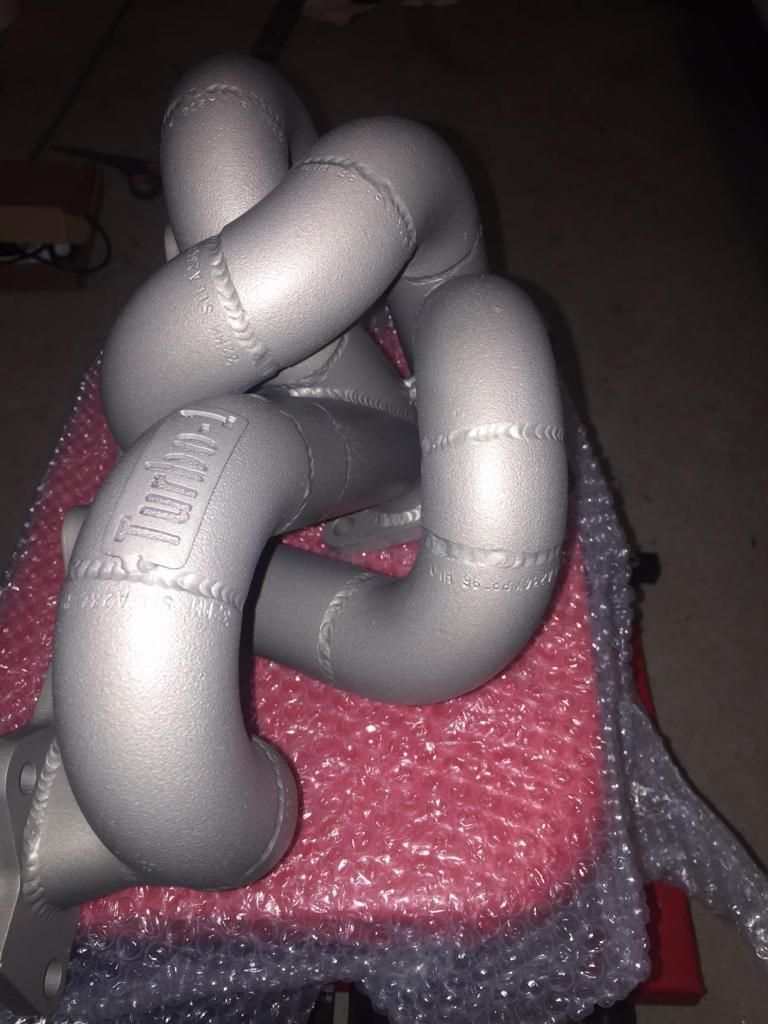
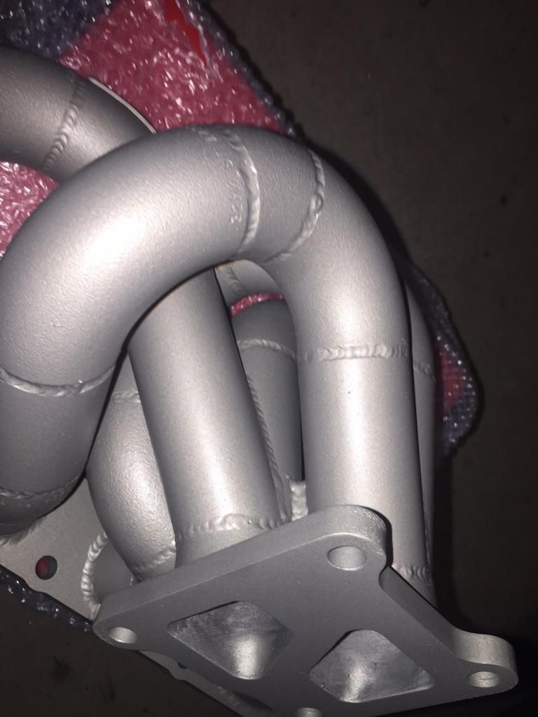
Also, i thought id post a pic of the 1.25" custom manifold and if you could provide me with your thoughts judging from its design/appearance?
( i thought this manifold would be unique due to the tapered outlet)
 Jan 5, 2015, 01:15 AM
#19
Evolving Member
Thread Starter
Join Date: Jan 2014
Location: Australia
Posts: 440
Likes: 0
Received 0 Likes
on
0 Posts
it seems to be more like a 'tag' that he puts on his hand made/welded products.
yeah the main reason i chose this was that its a SteamPipe material, having a taper from the flange and as you can see the collector is a bit different also, separated.
here are more pics as per your request:
so either i stick with this for the; Forced Performance BLACK or go for a 1.5
Last edited by wowzers; Jan 5, 2015 at 01:17 AM.
 Jan 5, 2015, 08:06 AM
#21

That looks a lot like the first stock replacement manifold I built.
When built right a 1.25" runner manifold will typically produce 50-75ft lbs more torque through the midrange than a 1.5" runner manifold. This is what I've seen on your typical 2 liter ~35r-ish sized applications. In my experience, with my manifolds, they remain efficient up to ~800whp with a typical 2 liter application. People have made more but top end power will start laying over.
1.25" manifolds are a bit more difficult to build properly as well. Like MrFred said, the exhaust port to tubing transition is critical and basically no one does it right...
Jan 5, 2015, 02:45 PM
#22
Stepped headers go from smaller to bigger mrfred. The idea is to maintain a high gas velocity near the valve to improve scavenging as the exhaust valve is closing.
What you are referring to with a set primary then some kind of reducing nozzle into the collector would be considered a pulse converter type manifold. They are used in diesel engine and are particularly effective at low engine speeds. However, it would likely be too restrictive at high engine speeds.
The transition to 1-1/4" is easy (I say that from experience), you just use a reducing cone and toss it into a press to ovalize it to match the stock head port. The stock head port has the same perimeter as roughly a 2" tube...
Personally, I'm done with weld-els. Columbia river bending offers some nice 11guage 180* mandrel bends with a 3" bend radius. It's also tubing so it's 1.75" and 2" OD which is better sizing for the 4G63. FAR superior to this weld-el stuff we've been using for 15 years.
Last edited by 03whitegsr; Jan 5, 2015 at 02:50 PM.
Jan 5, 2015, 05:52 PM
#23
What you are referring to with a set primary then some kind of reducing nozzle into the collector would be considered a pulse converter type manifold. They are used in diesel engine and are particularly effective at low engine speeds. However, it would likely be too restrictive at high engine speeds.
 Jan 5, 2015, 10:28 PM
#24
Picture or link to back up that statement?
Curious if we are actually talking about the same thing here.
Edit:
To answer my own question...and I preface this by saying I couldn't care less about F1...I believe you are referring to Mercedes using a log manifold?
If so, I'm not sure it would actually qualify as a pulse converter type manifold? Only pictures I have found show it under heat shielding. If it is infact a pulse-converter type manifold, it's very interesting as it goes directly against a pretty significant number of engineering white papers on this very subject.
That said....EVERYTHING on an F1 car is controlled by aerodynamics. Just because they use it doesn't mean it's good for making power at all. Likely just means it allowed them to move a heat exchanger or body surface to improve aero.
Last edited by 03whitegsr; Jan 5, 2015 at 10:58 PM.
 Dec 12, 2019, 06:02 AM
#28
Evolved Member

My own comparison: https://www.evolutionm.net/forums/ve...-toxicfab.html
Cliff notes is that they were very close to the same on the dyno, but the 1.5" manifold had better daily driving manners. Issue with the 1.25" primaries was that it felt a bit like it was being choked during off boost daily driving. It was nothing I could capture in a data log. Just seat of the pants difference in responsiveness.
Cliff notes is that they were very close to the same on the dyno, but the 1.5" manifold had better daily driving manners. Issue with the 1.25" primaries was that it felt a bit like it was being choked during off boost daily driving. It was nothing I could capture in a data log. Just seat of the pants difference in responsiveness.
Dec 12, 2019, 07:02 AM
#29
The ported OE manifold and the Toxicfab part represent two different designs. The external and material differences alone will result in differences in exhaust gas velocity, resonance, and heat. As such, we have no way of knowing how much of the perceived difference between them is strictly due to differences in internal runner dimensions. It is reasonable to assume that the OE part generates a higher pressure ratio at virtually all operating conditions, which affects VE globally.