When you click on links to various merchants on this site and make a purchase, this can result in this site earning a commission. Affiliate programs and affiliations include, but are not limited to, the eBay Partner Network.
Seems this thread died in the ***. Anyway, completed the installation of the GTR coils in sequntial spark mode. Ended up making a bespoke power supply with 14 gauge Raychem #44 wire to the harness plug, dedicated 14 gauge ground strap to the cylinder head, 30A sealed relay with a 15A sealed fuse holder. Built my own coils harness from 18 guage tefzel, spliced power and ground wires sealed with Raychem SCL and everything is then covered with raychem DR25. The harness is terminated into a 6-way Deutsch DT connector. Turned out really nice, fired up today for the first time and it ran well. I elected not to use the stock feed for the relay trigger, as this feed is on its own circuit with the ignition relay, lots of wire and the 10A fuse feeding it. Too many parts to fail that could take out the new system, so I am triggering it with an ECU switched 12v power signal that was previously used to power the narrowband o2 sensor.
I spoke to PRP in australia about the power feed situation and they advised that they don't really consider it a big deal. There's a 1000kw R34 GTR with 18 guage feed and ground apparently and that's doing just fine, so I guess the coil output must be pretty insensitive to dwell time with the GTR coils (or dwell voltage, as the case may be).
If you're running sequential ignition, the question I have is if you have two 16ga power feeds to supply the amperage demands during an individual coil's dwell time wouldn't that split the amps needed by 50% each to charge the coil in parallel? Or 7A and 7A instead of 14A through each of the stock wiring 12V feeds. I can understand if it was still a wasted spark setup simultaneously drawing amps for charging 2 coils could be pretty demanding on the stock wiring.
Edit: I should mention the above is with the assumption you'd be willing to run both power/ground circuits to all the coils in parallel.
Edit 2: I looked up the circuit diagram. The ignition coils have a 12V 16ga wire coming from the positive battery terminal with a 20A fuse and also has a branch from that same wire for the ECU. So.....probably better to run a separate line to the coils if you're drawing a lot of amperage.
Last edited by deeman101; Nov 3, 2020 at 12:53 PM.
If you're running sequential ignition, the question I have is if you have two 16ga power feeds to supply the amperage demands during an individual coil's dwell time wouldn't that split the amps needed by 50% each to charge the coil in parallel? Or 7A and 7A instead of 14A through each of the stock wiring 12V feeds. I can understand if it was still a wasted spark setup simultaneously drawing amps for charging 2 coils could be pretty demanding on the stock wiring.
Edit: I should mention the above is with the assumption you'd be willing to run both power/ground circuits to all the coils in parallel.
Edit 2: I looked up the circuit diagram. The ignition coils have a 12V 16ga wire coming from the positive battery terminal with a 20A fuse and also has a branch from that same wire for the ECU. So.....probably better to run a separate line to the coils if you're drawing a lot of amperage.
Just trying to unpack that, are you saying the stock setup has 2 x 16 ga feeds or you would build one with 2 x 16 ga feeds? The stock system has only 1 x 16 ga feed which is spliced to allow one power wire to run to each of the two OEM harness plugs. It's a long feed wire, it's power source is the Omron micro relay in the engine fuse/relay box and it's got a 10A fuse in the cabin as well. Not ideal from a resistance & voltage drop scenario, which is why the testing shows the voltage sags heavily during coil dwell with the stock feed setup.
Yes, running sequential spark vs wasted spark halves the load on the wiring as only one coil at a time is in a dwell state, there is no dwell overlap if you use the commonly found dwell times for the R35 coils. Wasted spark is charging two coils at once and firing one on the exhaust stroke, so it's double the charging load, double the charging/discharging related coil heat, and reduced coil and plug life. Given how antiquated the stock ECU is I changed this out awhile ago, and one of the advantages of aftermarket is the ability to run sequential spark. This also allows per cylinder knock control instead of cylinders being paired which is great too. Be crazy not to! If still on stock ECU, R35 coils in wasted spark mode on the stock power feed line is pretty tough going, they'll work but it is less than ideal.
Yea I checked the wiring diagram. Looks like only 16ga wire for both coils and the "ECS" or basically the ecu. I didn't see on the diagram that it was actually routed through the ECU plugs but that sounds reasonable.
Given that the ECU is drawing power over the same 16ga I'd favor running a seperate circuit to avoid potentially compromising ECU power. Even with a sequential ignition setup.
Yep that�s the same conclusion I came to. Just make a dedicated power supply and not worry about it again. It�s really quite straightforward to do.
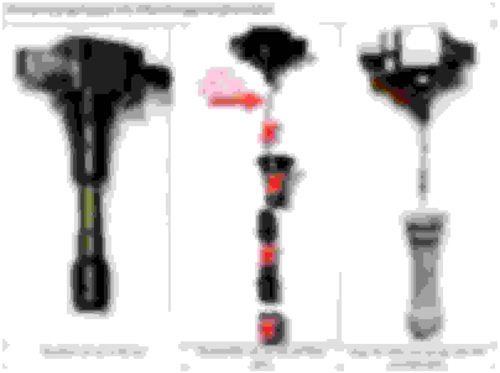
I got curious and bought some g37 (Hitachi IGC0002) coils from Rock auto. Like mentioned earlier the heads on these coil packs are supposed to be the same as the GTR and perform the same on test rigs but longer stalk length. Seems like they're even longer than OEM and won't sit under the valley cover. At least they're not too short like what mrfred found with the GTR coils. In any case they were much cheaper than R35 Hitachi coils even if I still need the PRP custom stalks to fit right.
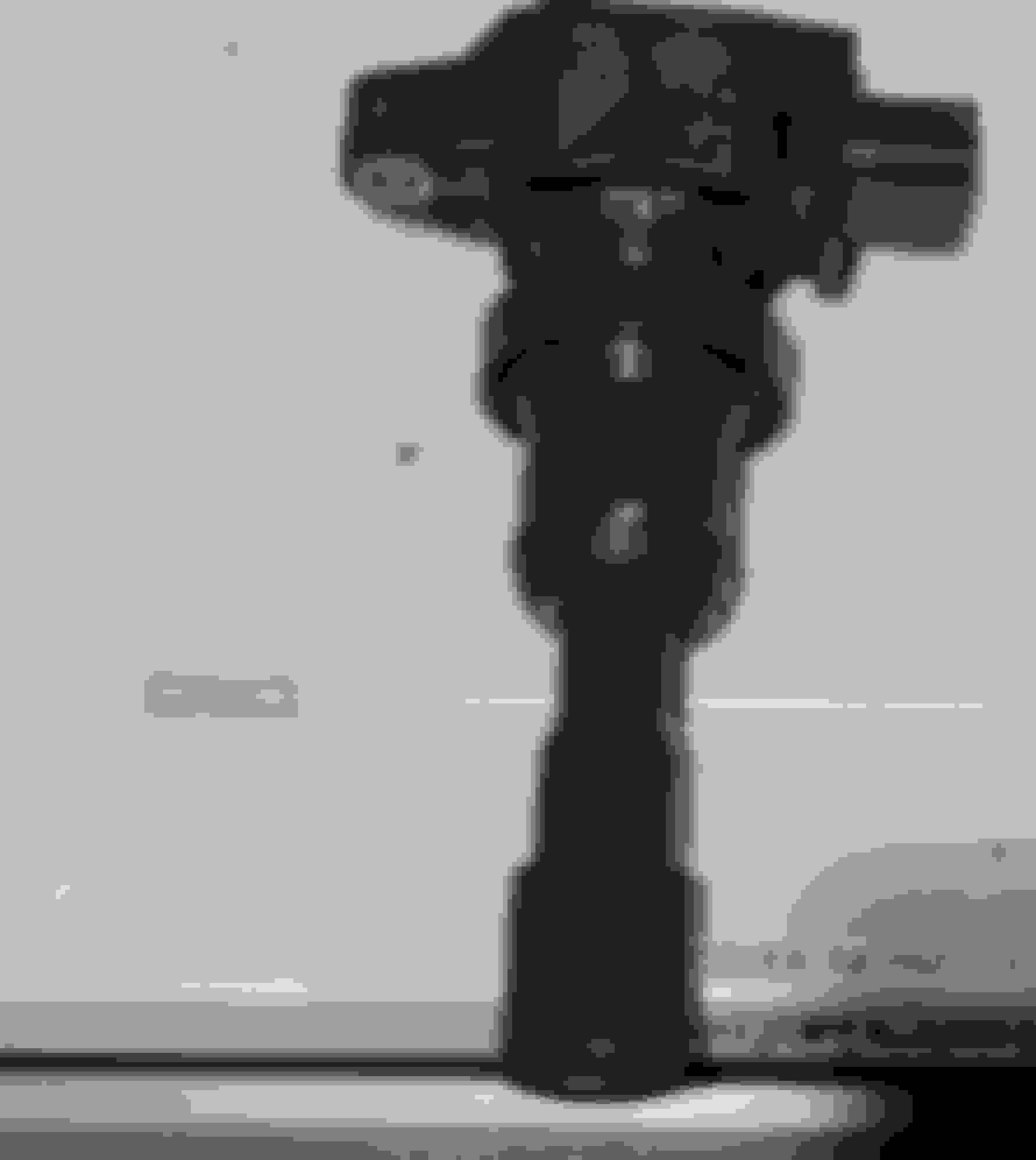
Actually I just tried something. I was able to put the Evo 8 coil stalk on it and the coil pack fit very nicely along with my spoolin up carbon mounting plate. Only thing is I needed to take out this fuse (seen to the left) and I'd need to cut a spring down to make it fit well. How necessary do people think that fuse is? Incidentally I think this one is blown....I'm measuring 1900 kohms right out of the box.
well bad news is, its not a fuse its a resistor. AFAIK you have to keep it. I'm not sure if the PRP stocks will work with your G37 coils without the GTR stocks. The PRPs retained the top half of the GTR stock but yours looks like its one piece in the picures?
Damn it I was starting to think that was actually a resistor. Not used to seeing one like this. Maybe it's possible to find another stalk that's Evo length but just has spring throughout the length (same as GTR/G37/PRP stalk). That way the resistor can stay.
The coil head looks exactly like in this pic from PRP and the resistor is in the same place. I'm highly confident it will work.
Damn it I was starting to think that was actually a resistor. Not used to seeing one like this. Maybe it's possible to find another stock that's Evo length but just has spring throughout the length (same as GTR/G37/PRP stalk). That way the resistor can stay.
The coil head looks exactly like in this pic from PRP and the resistor is in the same place. I'm highly confident it will work.
I was just thrown by the fuzzyness of your picture (on my screen anyway). I think your right that the top part of the stock will work just fine.
Actually I just tried something. I was able to put the Evo 8 coil stalk on it and the coil pack fit very nicely along with my spoolin up carbon mounting plate. Only thing is I needed to take out this fuse (seen to the left) and I'd need to cut a spring down to make it fit well. How necessary do people think that fuse is? Incidentally I think this one is blown....I'm measuring 1900 kohms right out of the box.
Found a fix. After some trial and error with different boots I found the NGK CPB Z004 boots work well for height and seal well in the wells. Also they put the GTR/g37 coil pack heads at the proper height for the spoolin up carbon mounting plate. Other than running a fused, relayed power line from the battery this should wire up like any other COP kit.
Bump on this thread !
once again, awesome work and information. I�m currently working on this aspect (but with � regular � Denso type coils (actually Delphi GN10312).
I was just wondering if someone has the definition for 96530006 rom for the last two table depicted by MrFred ? Now, I have d�finition for 4 tables, but I don�t found the two crancking related tables !
🙏
Great to see all the support for the stock evo ECU's and R35 coils! I'm about to throw a set of R35 Hitachi coils on my 1g 4g63 as well but my car is on an AEM ecu so i've got 4 coil outputs just waiting for the DSM/EVO 1-2 R35 COP conversion kit to arrive. Over kill for my turbo set up but happy to not ever worry about blowing out spark do to tired old coils. (i've always had great experience with the R35 coils on other engines lasting for years no problems as long as you don't over charge/overheat them.)
Thanks for all the testing. Quick one, you said on page 1 that the GTR coils draw 14A during the dwell period, but here you say the coils are at 11A when saturated. I'm a bit confused by the expression here. Isn't saturation a point at which maximal magnetic field strength has been formed in the coil, and when it collapses it triggers the maximal spark energy output? Saturation may take longer based on the incoming voltage/current fed to the coil from the power supply (ie: lower = longer dwell time required) but saturation is saturation, right?
The most telling detail is the voltage sag to 9.3v that you observed during the dwell period. Even with stock or Yaris coils, especially in wasted spark configuration, the stock power feed is inadequate. 16AWG wire is really only good for 10A constant in free air and it's really surprising to me that Mitsubishi undersized the feed to such an extent. Engine bay temps are high, and the circuit is fused at 10A - upgrading the ignition circuit fuse to 15A is really exceeding the wire rating and I'd suggest isn't a great idea. Was this test you performed where you obesrved the 9.3v at the end of the dwell period in wasted spark mode, or were you isolating a single coil only on the harness with no others connected and measuring it in situ while triggering it manually? I assumed this was in wasted spark mode, and you had all coils in place and the engine running but you were taking measurements from one coil. This would influence the results as you would have 2 coils in their dwell periods simultaneously. Similarly, did you perform the above current draw test in wasted spark mode with all the coils connected and running together?
I have almost finished converting my ignition system to sequential spark configuration, and I am debating the need to run a relay for a dedicated power supply for the ignition coils. I assume the spoolinup power harness is simply a relay with a fused power feed that uses the stock feed as the 12v relay on trigger signal (ie switched 12v trigger).
Notice in the photo that the charging curve is for the stock Evo coil wiring. There is enough resistance in the stock wiring that charge time is substantially longer, and even if I waited until saturation, I don't think the saturation current would reach the 14 A that I get with the SpoolinUp power hardness. But since you asked six months ago, you probably figured all that out already. :-)

 Nov 1, 2020, 12:41 PM