When you click on links to various merchants on this site and make a purchase, this can result in this site earning a commission. Affiliate programs and affiliations include, but are not limited to, the eBay Partner Network.
High Resistance at Connectors for Exhaust CAS + MAF
Evo GeneralDiscuss any generalized technical Evo related topics that may not fit into the other forums.
Please do not post tech and rumor threads here.
Sponsored by: RavSpec - JDM Wheels Central
High Resistance at Connectors for Exhaust CAS + MAF
Hi,
I'm currently backprobing/checking resistance on the connectors on my harness from the connector to the ECU to try to chase down a phantom knock issue. So far every connector I've done I've gotten around .2-.5 ohm of resistance, but the MAF sensor ground I'm getting 3.4 ohm and the exhaust cam angle sensor I'm getting 2.5 ohm when backprobing to ECU Pin 34 (Sensor Ground, common ground for cam/crank angle sensors, MAF, MAP).
I stripped the sleeving on the harness to expose the wiring a good 2-3 feet from the connector and I can't find any visible damage to the MAF wiring + the exhaust CAS wiring had funky looking insulation for the first 6 inches past the connector (I spliced in a new connector w/pigtail a good 18in from the back into "clean" wiring). The insulation on that wiring was melted from the crank angle sensor ground eyelet getting hot at some point. After replacing the exhaust cam angle sensor wiring by going almost 2 feet back into the harness...it's still giving me the same resistance. Am I chasing my tail over something that's supposed to be normal or is there something wrong that I'm missing out on? I checked my test leads + multimeter and they're fine + the other sensors on that gnd give under 1 ohm of resistance. Please help before I buy a whole used harness and swap it out!
I hate to tell you this but you are going about it wrong. You should be checking for voltage drops- not resistance problems. Your meter will load the circuit with almost no current- hence things may show good.
You would be wiser to get a cheap scope and look for glitches and dropouts with the car running. If you want something cheap and portable I suggest u-scope from aes wave.
That will be later if the car keeps giving me issues. But honestly I'm tempted to buy a good used harness for any future problems. I figured out my issue. It was a combination of weak batteries on my multimeter, crappy test leads, my backprobe pin fitting loose enough in pin 34 to give additional resistance (noticed this after I removed the pin from the connector and got .3-.5 ohms...used a 1.2mm flathead as a pin after and it worked better), and possible corrosion on the ECU plugs and pins (I left it with Deoxit D100L overnight after working the connectors on/off the ECU a few times). Now 0.3-0.5 ohm every time every ground going to Pin 34 when before it was 2.5-4 ohm sometimes climbing as high as 18-60 ohm if I left the multimeter on the MAF or exhaust cam angle sensor ground.
Long story short, check your connections and use Deoxit on everything.
Second Update. This was the actual issue. The pin I was testing had a micro fracture that became a actual fracture when I started aggressively back probing. Decided to retest, got 2.4 ohm, then took the pin out the ECU connector and played with it. All the screwdriver did was just tighten the fracture back up just enough to give me a acceptable resistance. I retested just running the multimeter checking for resistance between the exhaust CAS gnd wire and pin 34 (stripped) and got a acceptable resistance (.6ohm).
Fortunately replacement pins are available at SpoolinUp however I did notice two things
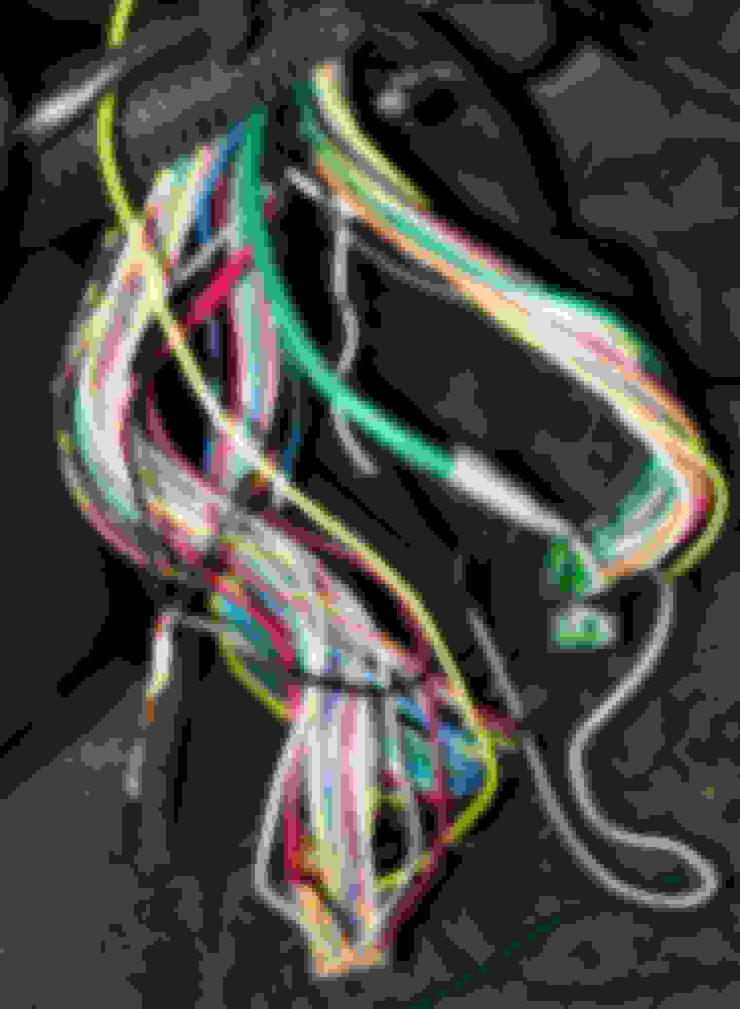
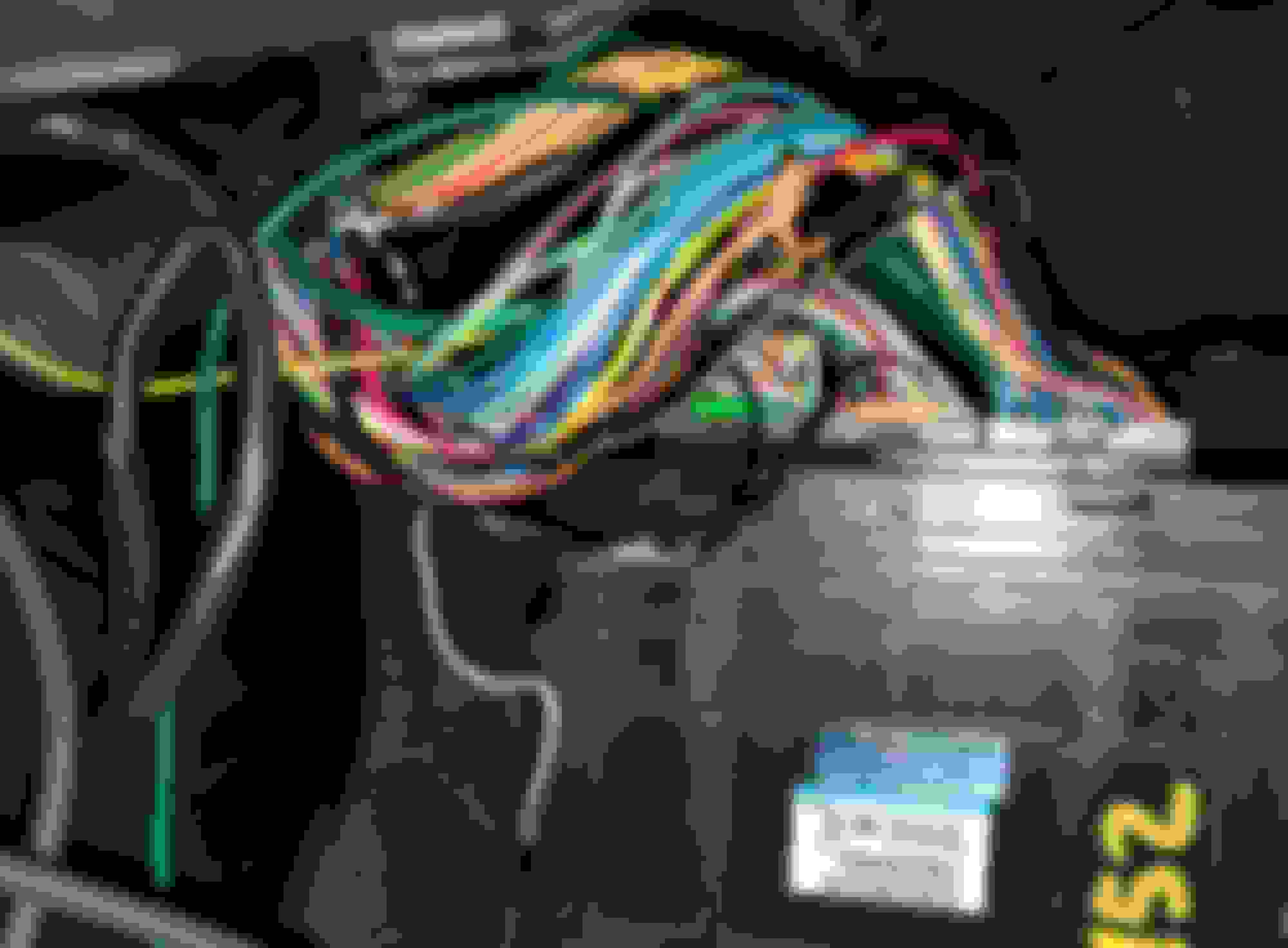
Is it normal for that ground wire with the broken pin (pin 34, blue plug) to run a little short? I did notice it was always under "tension" and noticably shorter than the rest of the wires on the ECU plugs.
Second, is this factory? There's a four way ground coming into pin 49 on the ECU side (analog ground for O2/TPS).
The car had an AEM V1 at some point in its life but was reverted back to stock ECU. I did notice the splice for the O2 signal wire (pin 71) but interestingly enough I also noticed one of the ground wires going into the 4 way splice for pin 49 is wrapped around the O2 signal wire. There's also a splice coming off ECU pin 1 (injector #1 signal) that was removed similar to the other splice at 71.
 Jun 18, 2024, 03:08 AM