
How to make a professional Battery/Alternator/Grounding cable
 Nov 30, 2007, 08:52 PM
#1
Account Disabled
Thread Starter
iTrader: (9)

Join Date: Apr 2007
Location: AZ, currently in Space Coast, FL
Posts: 460
Likes: 0
Received 0 Likes
on
0 Posts
How to make a professional Battery/Alternator/Grounding cable
Power management is often one of the most overlooked modifications on any car. So many people install huge Stereos, larger batteries, and other items that draw so much power, yet they often neglect the wiring, and leave it stock. This can cause the factory wires to overload, heat, and could cause fires.
This is how to make a high performance, professional grade power/ground wire.
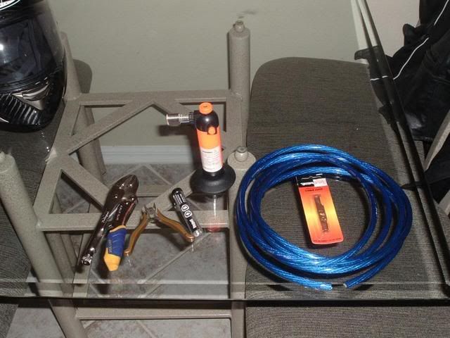
Needed:
-Mini torch (you can get these at nearly any electronics, Tools, or Home improvement shop. I got mine at Harbor Freight for like $6)
-Electrical Solder, Get alot!
-1/2" or larger shring wrap (to fit over the wire)
-High Quality power wire (you can get this at any good custom stereo shop. the main things to look for are flexibility, and quantity of fine copper wire)
-copper lugs (Ace Hardware sells these in the welding sections)
-Vice, or vice grips
-small dykes (wire cutters for you pervs)
-razor knife
First tip: Only do one side at a time. By this, I mean do one side COMPLETELY, before cutting the wire to length. This is because sometimes the side does not come out well, and you have to clip it off, and start over. Each time you clip, you lose about 1/2"-3/4" in length... this becomes too short very quickly.
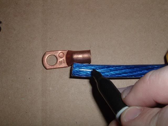
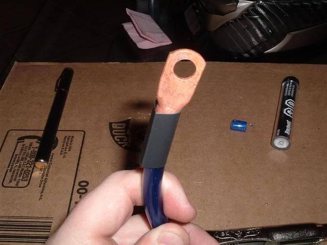
OK, to start, place the end of the wire next to the copper lug. line up the end of the wire to just passed where the lug starts to taper down. Mark the wire at this length all the way around. Also place a mark from the measured line straight out to the tip.
Using the razor knife, cut through the plastic jacket all the way around. I have found sometimes it's easier to roll the between a surface and the knife to cut all the way around.
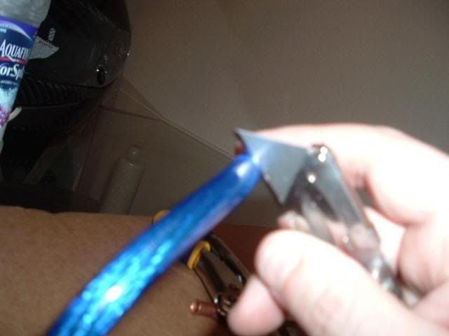
Once you have cut all the way around, cut along the line you made from the now exsisting cut, to the tip of the wire. This is to release the tension of the jacket on the wire to release it better

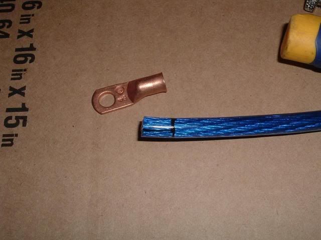
Now pull the sleeve off of the wire. Be careful not to bend the wire too much, as this will disturb the wire under and make it hard to push into the lug later on.
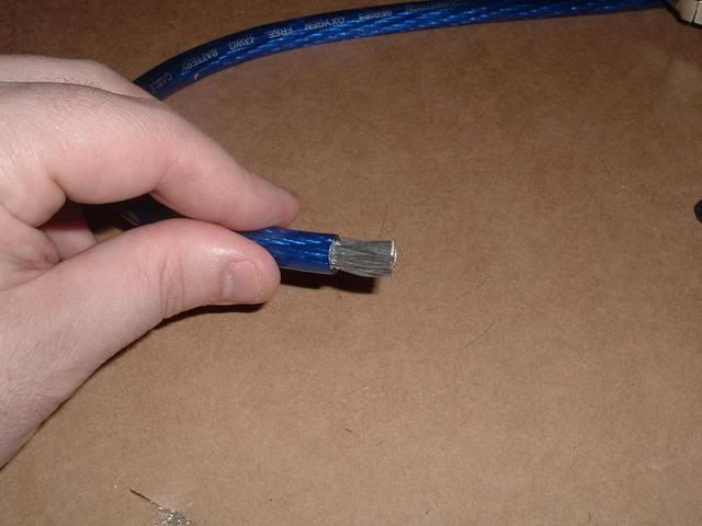
Once the jacket is off, clean up the loose wires that were cut when you pulled the jacket off. a few (less than 30) is ok... but if you cut a big chunk out, start over.
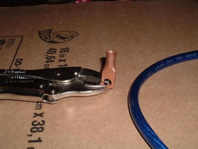
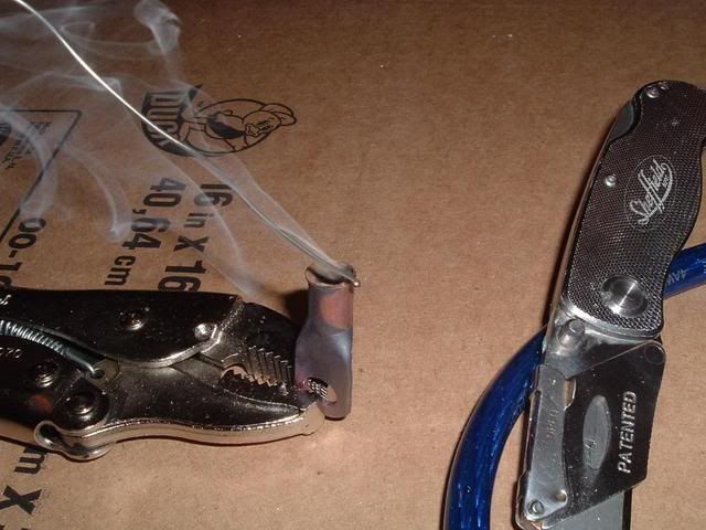
Set the wire aside, and place the lug in the vice or vice grips so that the opening makes an upwards facing cup
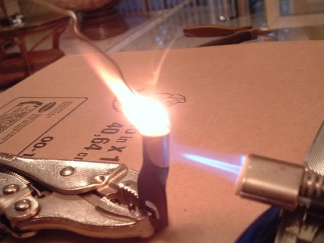
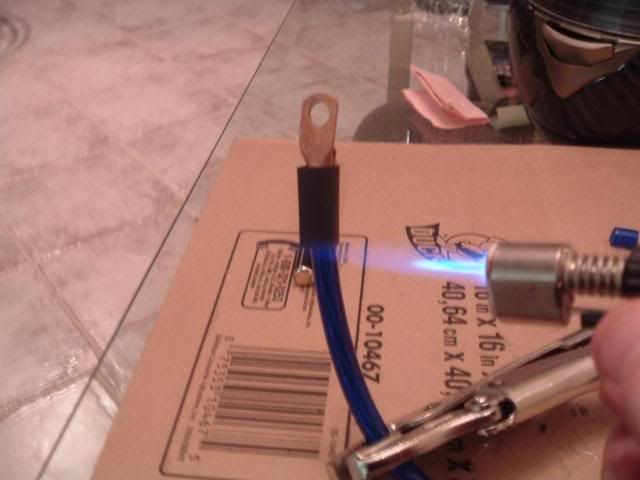
Using the mini torch, heat the copper for a while, typically it will take on a blueish color around where you're heating it. You want to heat it enough so that the copper is VERY hot, but not so much that you are blackening the copper.
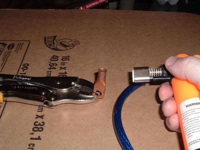
While still heating the copper, start to fill the cup with solder. When doing this, often the flux in the solder will flame up and burn off. This is normal, but be careful not to burn yourself.
BE CAREFUL NOT TO INHALE THE FUMES!!!
Fill the cup approximately 1/2 full with molten solder.
Now, very carefully, but quickly, push the wire into the cup of molten solder. Solder will often times over-flow out of the cup, so be sure there is something under to catch the solder and your table won't get burned.
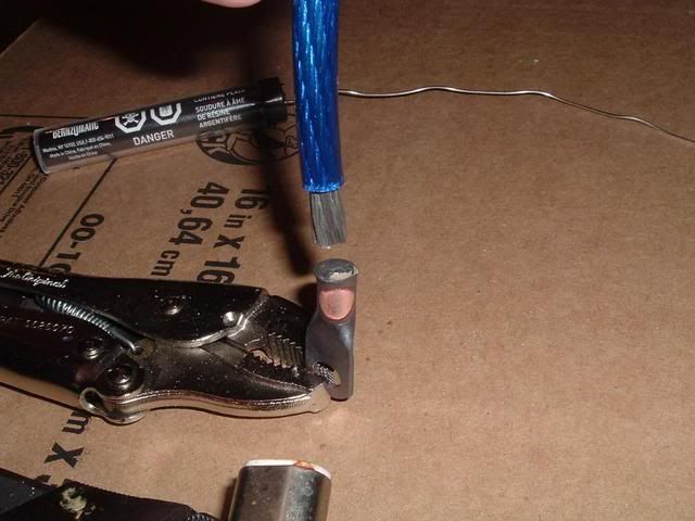
Push the wire all the way till the plastic touches the copper lug. Once the copper wire gets pushed into the solder, the wire will abosorb much of the heat of the solder, and the solder will become solid very quickly. If you were fast enough, the bond will be made a second or two after the plastic jacket touches the copper lug. If you were too slow, you won't get all the wire into the lug. Heat the lug till the wire melts out, cut off the end of the wire and start over.
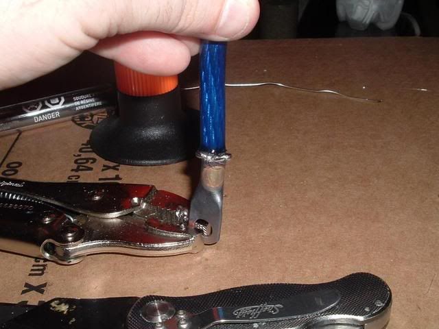
Once you get the wire all the way into the lug, pull the cable out of the vice/vice grips and quench it in water. This will remove most of the heat from the lug and cable so it can be handled.
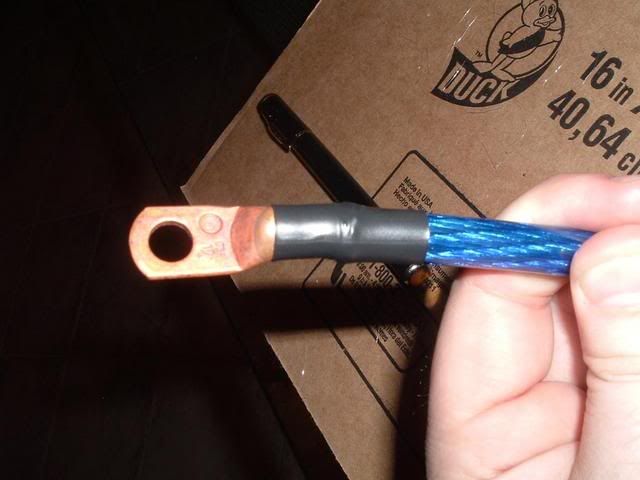
Now, typically there will be a few straggler wires that are poking out of the cup. This is ok. Use your small nippers and cut those few wires off. Also if the wire jacket mushroomed out when it got hot, you can cut this spare plastic away so that everything is flush.

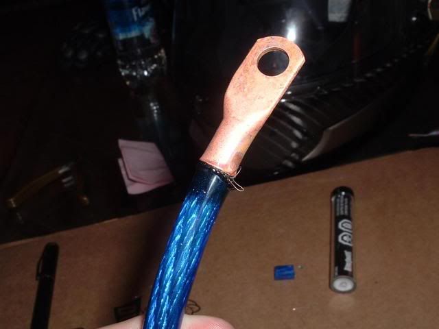
You are almost there. Cut a 1" piece of shrink wrap, place it over the wire, and using a heat-gun, lighter, or the mini torch with some distance... Heat the shrink wrap so that it bonds the copper lug and the wire jacket together.
Now place the wire in the place you want it. Measure to length, and do the same with the other side. If you are new to this, I recomend giving yourself an extra 3"s of length just to be safe.
Now, General guidelines:
- Do not replace your wires if you are not comfortable with doing electrical work, or do not understand the principals of automotive electronics.
- if you do this, and your car burns down because you did a poor job, it's your fault
-even a correctly made wire, if installed correctly can short and burn your car down
Now, I personally am replacing the following wires with 1/0 (pronounced "one-ought") wire.
-Alternator to positive lead of battery (in blue 1/0 Tsunami wire) (REPLACEMENT)
-Alternator chassis to vehicle chassis (in silver 1/0 Tsunami wire) (NEW WIRE)
-Negative terminal of battery to vehicle chassis point above (in silver 1/0 Tsunami wire) (NEW WIRE)
-Negative terminal of battery to stock grounding point (in silver 1/0 Tsunami wire) (REPLACEMENT WIRE)
Dominick Iraggi (who builds high output alternators) recomends running 4 gauge wire parallel to the stock wire, rather than replacement. I believe this is so that you have two wires, one to act as back-up if there is a failure. I personally am going to just replace with a larger wire. Do what you feel is best.
Pictures are to follow soon. I just can't find my camera cable at the moment, but don't want to re-type this later :-)
This is how to make a high performance, professional grade power/ground wire.
Needed:
-Mini torch (you can get these at nearly any electronics, Tools, or Home improvement shop. I got mine at Harbor Freight for like $6)
-Electrical Solder, Get alot!
-1/2" or larger shring wrap (to fit over the wire)
-High Quality power wire (you can get this at any good custom stereo shop. the main things to look for are flexibility, and quantity of fine copper wire)
-copper lugs (Ace Hardware sells these in the welding sections)
-Vice, or vice grips
-small dykes (wire cutters for you pervs)
-razor knife
First tip: Only do one side at a time. By this, I mean do one side COMPLETELY, before cutting the wire to length. This is because sometimes the side does not come out well, and you have to clip it off, and start over. Each time you clip, you lose about 1/2"-3/4" in length... this becomes too short very quickly.
OK, to start, place the end of the wire next to the copper lug. line up the end of the wire to just passed where the lug starts to taper down. Mark the wire at this length all the way around. Also place a mark from the measured line straight out to the tip.
Using the razor knife, cut through the plastic jacket all the way around. I have found sometimes it's easier to roll the between a surface and the knife to cut all the way around.
Once you have cut all the way around, cut along the line you made from the now exsisting cut, to the tip of the wire. This is to release the tension of the jacket on the wire to release it better
Now pull the sleeve off of the wire. Be careful not to bend the wire too much, as this will disturb the wire under and make it hard to push into the lug later on.
Once the jacket is off, clean up the loose wires that were cut when you pulled the jacket off. a few (less than 30) is ok... but if you cut a big chunk out, start over.
Set the wire aside, and place the lug in the vice or vice grips so that the opening makes an upwards facing cup
Using the mini torch, heat the copper for a while, typically it will take on a blueish color around where you're heating it. You want to heat it enough so that the copper is VERY hot, but not so much that you are blackening the copper.
While still heating the copper, start to fill the cup with solder. When doing this, often the flux in the solder will flame up and burn off. This is normal, but be careful not to burn yourself.
BE CAREFUL NOT TO INHALE THE FUMES!!!
Fill the cup approximately 1/2 full with molten solder.
Now, very carefully, but quickly, push the wire into the cup of molten solder. Solder will often times over-flow out of the cup, so be sure there is something under to catch the solder and your table won't get burned.
Push the wire all the way till the plastic touches the copper lug. Once the copper wire gets pushed into the solder, the wire will abosorb much of the heat of the solder, and the solder will become solid very quickly. If you were fast enough, the bond will be made a second or two after the plastic jacket touches the copper lug. If you were too slow, you won't get all the wire into the lug. Heat the lug till the wire melts out, cut off the end of the wire and start over.
Once you get the wire all the way into the lug, pull the cable out of the vice/vice grips and quench it in water. This will remove most of the heat from the lug and cable so it can be handled.
Now, typically there will be a few straggler wires that are poking out of the cup. This is ok. Use your small nippers and cut those few wires off. Also if the wire jacket mushroomed out when it got hot, you can cut this spare plastic away so that everything is flush.
You are almost there. Cut a 1" piece of shrink wrap, place it over the wire, and using a heat-gun, lighter, or the mini torch with some distance... Heat the shrink wrap so that it bonds the copper lug and the wire jacket together.
Now place the wire in the place you want it. Measure to length, and do the same with the other side. If you are new to this, I recomend giving yourself an extra 3"s of length just to be safe.
Now, General guidelines:
- Do not replace your wires if you are not comfortable with doing electrical work, or do not understand the principals of automotive electronics.
- if you do this, and your car burns down because you did a poor job, it's your fault
-even a correctly made wire, if installed correctly can short and burn your car down
Now, I personally am replacing the following wires with 1/0 (pronounced "one-ought") wire.
-Alternator to positive lead of battery (in blue 1/0 Tsunami wire) (REPLACEMENT)
-Alternator chassis to vehicle chassis (in silver 1/0 Tsunami wire) (NEW WIRE)
-Negative terminal of battery to vehicle chassis point above (in silver 1/0 Tsunami wire) (NEW WIRE)
-Negative terminal of battery to stock grounding point (in silver 1/0 Tsunami wire) (REPLACEMENT WIRE)
Dominick Iraggi (who builds high output alternators) recomends running 4 gauge wire parallel to the stock wire, rather than replacement. I believe this is so that you have two wires, one to act as back-up if there is a failure. I personally am going to just replace with a larger wire. Do what you feel is best.
Pictures are to follow soon. I just can't find my camera cable at the moment, but don't want to re-type this later :-)
Last edited by TempeRacerGuy; Dec 12, 2007 at 09:23 PM.

 Dec 12, 2007, 09:45 PM
#3
Account Disabled
Thread Starter
iTrader: (9)
Join Date: Apr 2007
Location: AZ, currently in Space Coast, FL
Posts: 460
Likes: 0
Received 0 Likes
on
0 Posts
I have used monster wires in the past, and they are a quality wire. However they are typically very expensive. Also with their "power flex" model, they substitute the center braid of wire with a "magnetic flux tube" Their literature says this improves voltage transfer, but I believe it's purely to make their wire bend easier.
With the 4 gauge Oxygen Free Competition Tsunami wires I used, I am getting zero voltage drop with full load along the nearly 20 feet of power cable I used.
I did mis-post however, as with the 1/0 wires, I didn't use Tsunami, I used the new Stinger Hyper Twist. for a full 1/0 wire, you can bend it to a 3/4" radius bend with no stress on the jacket or internal wires. I am very impressed with this wire. It is an OFC with over 3600 strands in a reverse twist layout. This lets them put use more wires while still maintaining an extremely flexible bend radius.
Dec 12, 2007, 10:13 PM
#4
Evolving Member
iTrader: (2)

Join Date: Apr 2007
Location: LA, CA
Posts: 101
Likes: 0
Received 0 Likes
on
0 Posts
I diagree with your soldering technique. First, by putting in all the solder first, you just burned off half the purpose of the flux, cleaning the wire TOO. It's not just there to clean the lug, or make fire. Second, by just shoving the wire INTO the molten solder (which will solidfy very quickly even without cold wire going into it) you aren't getting the solder into and through all of the wire.
A better technique is to strip it back a little farther (Don't be afraid to show a little wire) and stick the wire in the lug. Then heat the lug WITH THE WIRE IN IT. When the heat is soaked all the way through, start adding solder on the opposite side of your heat source. It will suck the solder in. You will know what I am talking about as soon as you do it. Expecially if using an iron, it may take a little while to heat up completely, and may melt a little of the insulation on the wire. No big deal, that's what shrink tubing is for.
Hold the lug so the wire comes out vertically upward or horizontally but not vertically downward. If not the solder can creep down the wire too far outside of the lug because of gravity. This isn't bad, it just uses extra solder and makes it stiff where the solder is in the wire.
Then, when solder shows in the wire on the other side, you know it is completely soaked through, and bonded to the copper and wire.
When just sticking the wire into the molten solder, it isn't going to be as strong as my method because it's partially cooling as you stick it in and also not throughout the wire. I would seriously at least re-heat the lug really good after you stick it in, or the wire could pull out especially since flux didn't clean it off, and the solder wasn't far enough above the liquidous line and you may have had alpha + liquid for most of the contact of the wire with the solder.
To each his own, I am pretty sure my method would be a slight bit better. But, great writeup and nice pictures!
Last edited by mikespike2; Dec 12, 2007 at 10:22 PM.
Dec 13, 2007, 04:57 PM
#5
Account Disabled
Thread Starter
iTrader: (9)
Join Date: Apr 2007
Location: AZ, currently in Space Coast, FL
Posts: 460
Likes: 0
Received 0 Likes
on
0 Posts
I agree mikespike, by putting it in, and then soldering you will get a stronger bond. and if I were doing this on an aircraft, I would crimp, then solder as he mentions.
One thing I didn't mention and may be causing some confusion, is that I only use this technique for large power wires (4 gauge and up) So, with this great of a mass of copper, the heating from the lug will transfer FAR up the PVC jacket of the wire, and cause the PVC to melt away from the wire, making the wire unsupported in the jacket. For smaller wires, a soldering iron would be sufficient, but anything 4 gauge and up a torch is needed.
Your way will make a stronger bond, no doubt, however I have made hundreds of wires this way for the past 20 or so years, and I have never had one come apart.
One way to improve my method above, which I think would be a good compromise, would be to keep heat on the lug as you are pushing in the wire. This would keep the solder at a high enough temperature to ensure a good bond.
Thank you mike, I agree and appreciate your input.
Dec 13, 2007, 05:09 PM
#6
Newbie

Join Date: Dec 2007
Location: Princeton, NJ
Posts: 44
Likes: 0
Received 0 Likes
on
0 Posts
also, heating something with a propane torch, a pair of vicegrips, and a piece of cardboard is a pretty irresponsible thing to be doing inside your house without serious eye, face, and breathing protection along with standard fire safety practices. seriously man, get a garage with a clean, concrete floor and a steel workbench, throw the stuff in a vice and use a real torch.
you're heating up a volatile substance, and you're protecting your flammable materials (carpet, couch, you, etc.) with another flammable material (cardboard). spill that flux chunk on the cardboard, tell me how long it takes your house to burn down.
Dec 13, 2007, 09:08 PM
#7
Evolving Member
iTrader: (10)

Join Date: Jul 2007
Location: Manassas, VA
Posts: 170
Likes: 0
Received 0 Likes
on
0 Posts
If anybody can take pictures of the install when they get around to it ,that would be awesome! If I get to it first, I will, but I just want to see what others are doing to get this thing installed.
Trending Topics
Dec 15, 2007, 08:18 AM
#8
Account Disabled
Thread Starter
iTrader: (9)
Join Date: Apr 2007
Location: AZ, currently in Space Coast, FL
Posts: 460
Likes: 0
Received 0 Likes
on
0 Posts
fixed it for you. there is no such thing as no voltage drop, much like there is never an absence of friction. in anything where work is being performed (something is being moved, energy is being transfered, something is being heated, etc.) there will always be parasitic losses.
also, heating something with a propane torch, a pair of vicegrips, and a piece of cardboard is a pretty irresponsible thing to be doing inside your house without serious eye, face, and breathing protection along with standard fire safety practices. seriously man, get a garage with a clean, concrete floor and a steel workbench, throw the stuff in a vice and use a real torch.
The purpose of this how-to, was to show people that they can do this at home without special tools. I do have a garage, vice, hydrolic presses, specialty engine tools, blah be de blah blah blah... but the vast majority of people on here do not. I wanted to show how it can be done for a bare-minimum of cost. But I appreciate your suggestions mom.
Oh, and it's a butane torch, not a propane torch.
you're heating up a volatile substance, and you're protecting your flammable materials (carpet, couch, you, etc.) with another flammable material (cardboard). spill that flux chunk on the cardboard, tell me how long it takes your house to burn down.
besides, both the flux and solder are non-volatile, they are stable, don't vaporize easily, and don't have a high vapor pressure, they meet no requirements to be clasified as "volatile"
I didn't write this to meet OSHA requirements, for god's sake, I was showing how something can be done at home for a bare minimum of cost with quality results.
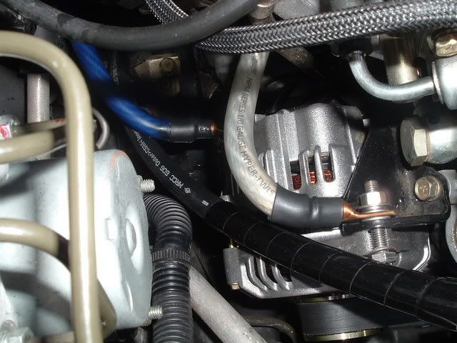
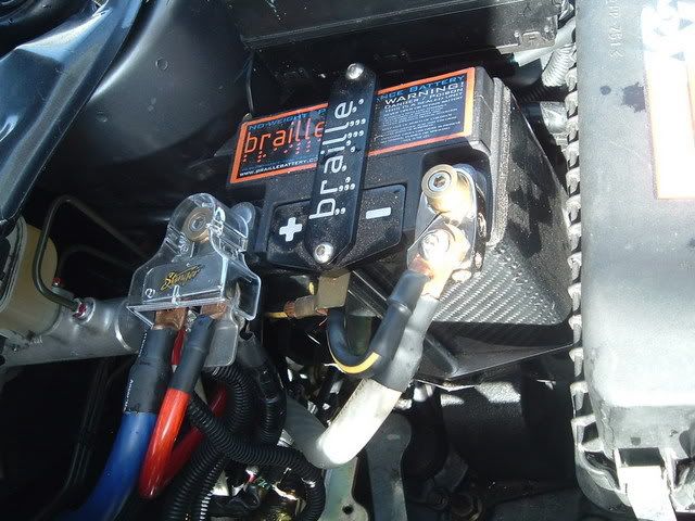
YT, here are some pics of the wires installed:
Last edited by TempeRacerGuy; Dec 15, 2007 at 08:57 AM.
Dec 29, 2007, 06:08 PM
#9

Why not just buy some flux and dip the wire in that? By tinning the wire, you're getting the solder in all the right places. Then, when you're going to solder the lug and the wire together, you won't need as much solder and it will bond a lot better. That way, the wire won't short and it also won't burn your car out. It'll also help getting those pesky frayed wires out of the way so you can easily slide the wire into the lug.
Jan 8, 2008, 02:03 PM
#11
Evolving Member
iTrader: (15)

Join Date: Oct 2005
Location: Livingston NJ
Posts: 286
Likes: 0
Received 0 Likes
on
0 Posts
Great write up! Questions though-
For the negative terminal to chassis and the alternator casing to chassis wires, exactly which points did you use? Or is this question a moot point because the grounding points will be really obvious?
For the negative terminal to chassis and the alternator casing to chassis wires, exactly which points did you use? Or is this question a moot point because the grounding points will be really obvious?
Jan 17, 2008, 01:45 AM
#12
Evolving Member
iTrader: (1)
Join Date: Jun 2005
Location: mitchigan.
Posts: 108
Likes: 0
Received 0 Likes
on
0 Posts
Out of curiosity, why not just crimp the end? In the past, I have never used this method for the same outcome that you were showing. I just crimp the end, but also apply heat shrink over it. I've actually done a "hang" test with the crimped end. By putting it over a screw on the rafter in the garage, and then hanging from the wire. It held just fine. This looks like a good method, but I am really curious on how well it would hold with the same type of barbaric test. 
Jan 17, 2008, 04:37 AM
#13
Evolving Member
iTrader: (22)
Join Date: Jan 2007
Location: North East
Posts: 493
Likes: 0
Received 0 Likes
on
0 Posts
All you did was make a giant cold solder joint.
You need to heat the wire and let the solder work it's way into the strands. That method is going to fail at some point and pop out of the connector.
As for the voltage drop, look up ohms law and do the math. There is always voltage drop. E=IxR, if your subwoofer is a constant 2 ohm load, then the only way to get more power is to increase voltage or current. We know voltage will not increase because we have 12volt batteries and our alternators will not go over 14volts because they are regulated. So that leaves current or amperes. So after you get the threshold for the current, voltage WILL drop.
basic electricity 101.
Jan 21, 2008, 10:30 AM
#15
As for the voltage drop, look up ohms law and do the math. There is always voltage drop. E=IxR, if your subwoofer is a constant 2 ohm load, then the only way to get more power is to increase voltage or current. We know voltage will not increase because we have 12volt batteries and our alternators will not go over 14volts because they are regulated. So that leaves current or amperes. So after you get the threshold for the current, voltage WILL drop.
basic electricity 101.
basic electricity 101.
Subwoofers are not a constant 2 ohm load. They have a complex impedance that is coupled with mechanical system. There's a great big impedance spike at the resonant frequency and the impedance starts increasing above around 100 Hz.
Your input voltage is 14.4V or whatever your particular voltage regulator controls to, but this is a DC voltage input to the amplifier. The amplifier bumps up the voltage. The one amplifier design I've studied in detail used + and - 80V for the power rails. From an impedance standpoint, the amp looks like a changing impedance as its instantaneous power output goes up and down. This draws different amounts of current from the same 14.4 volts.
If the instantaneous impedance of the amp drops to within a magnitude or so of the impedance of the wiring, you will start seeing measurable voltage drop on your power feeds. There's also a source resistance associated with your alternator that will cause voltage drop (this is what you see when a car's lights dim with the subwoofer).
BTW, the method described here won't create the best electrical connection. There's enough surface area there that it's probably ok. There's probably enough heat stored in the lug that its actually not a cold solder joint. Its just not the way I would do it.