
AEM Tru Boost Gauge Install
 Jan 27, 2009, 09:26 AM
#1
Evolving Member
Thread Starter
iTrader: (17)
Join Date: Apr 2007
Location: New York,NY
Posts: 384
Likes: 0
Received 0 Likes
on
0 Posts
AEM Tru Boost Gauge Install
AEM Tru Boost Gauge Install Guide
Please remember to disconnect your battery before wiring power.
This is a rather simple install but if you don't feel confident in doing it then please don't. You are responsible for your own work
Its also a good idea to temp wire everything before you solder. Test that it works, then solder everything together.
Link to PDF Instructions http://tunertools.com/prodimages/AEM...st_30-4350.pdf
First its a good idea to remove the intake to give you some room to work.
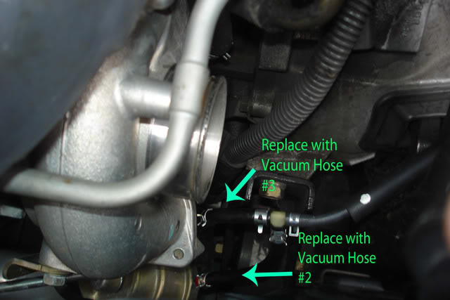
1) Remove stock vacuum lines from stock boost solenoid and wastegate + turbo.
You can not use these lines for the install due to the factory boost pill.
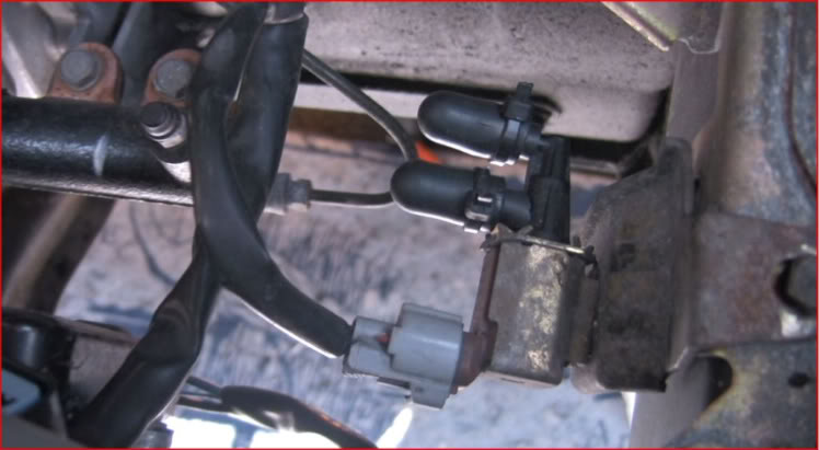
2) Cap off the stock solenoid but do not unplug it.
I used some small vacuum line caps, zip tied and taped up the solenoid.
3) Mount the AEM Boost solenoid.
Link to one possible location.
https://www.evolutionm.net/forums/ev...installed.html
I mounted mine temporary on my battery tray bar. Temp Spot :-(

A good place would be where the stock solenoid is.
With the stock air box its a little tricky to get it on there just right.
Double sided tape and some zip ties should help.
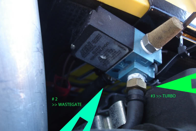
4) Run vacuum lines.
#2 on the left goes to the waste gate
#3 goes to the turbo.
#1 is capped

5) Feed the long part of the harness, the one with just 2 wires, from the cabin, through the firewall. There is a hole on the passenger side against the firewall.

*TIP* tape the wire to a small pole or something(<< no jokes)) then push it through the hole, once its through, untape it and pull wire through
Once its in the engine bay,I ran this wire across the back of the firewall, around the battery, towards the aem solenoid.
The 2 Brown wires from the solenoid connect to the 2 long wires from the harness.
Polarity does not matter so connect 1 for the red and 1 for the black. Solder tape
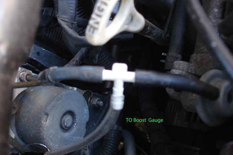
6) T the FPR hose for pressure sensor.
ZIP TIE CONNECTIONS
The clear hose in pic connects to the gauge.
7) Push vacuum line through firewall to the gauge.
8) Decide on gauge placement and tuck wires
9) Wire the Gauge

I extended both the power and the ground wires.
A)Wire both Red wires to 12v switched power.
I soldered both of them together to my extension wire-then spliced into radio 12v switched.
B)Wire Ground >>> Extened wire then tapped into the Clock for a Ground. You can use Radio ground or a good Bolt Ground.
C)Orange Wire >>>Scramble Boost>>> Did not use, tape it to harness out of the way
D)Gray Wire>>>> Warning Light>>>>> "" "" "" "" ""
10)Connect vacuum line to the back of the gauge. Zip tie for protection.

11) Reconnect battery and check that everything works.

12) Setup gauge following instructions from AEM manual.
Unl = PSI, BAR, PAS
SCb = Scramble boost settings - Skip
SCr = Scramble boost duration - Skip
SEn = Pressure sensor Select I for Internal- E for optional external sensor
ALA = Boost alarm setting.
gAE = Waste Gate Crack Pressure see below
FUL = Set the full scale for sweeping lights.
Boost setting A= Duty cycle settings
Boost setting B= B duty cycle settings
Boost setting tips
Waste Gate Crack Pressure (gAE)
From the Manual
"Enter the boost pressure at which the waste gate starts to open. The Tru Boost
will keep the boost solenoid open from 1 psi until boost exceeds the selected value.
This value can be adjusted to reduce lead in boost spikes or reduce spool up time."
Most people say set this to 11.5, Which is the stock wastgate spring pressure, then adjust your duty cycle setting until you hit the boost # you want.
This mainly effects spool up and spikes.
Boost Setting A-B / Duty Cycle Settings
Every car will react to this setting differently so there is no "right" value for this number.
I will post different results that people have attained but it is best to self tune this value until you hit the PSI that you want.
This will also change based on the weather. So if it gets cold where you live, or for winter, you may need to lower this setting.
If anyone would like to contribute tips on SPR pressure and Duty Cycle settings, or if you have anything else to contribute please post or msg me and i'll update.
Please remember to disconnect your battery before wiring power.
This is a rather simple install but if you don't feel confident in doing it then please don't. You are responsible for your own work
Its also a good idea to temp wire everything before you solder. Test that it works, then solder everything together.
Link to PDF Instructions http://tunertools.com/prodimages/AEM...st_30-4350.pdf
First its a good idea to remove the intake to give you some room to work.
1) Remove stock vacuum lines from stock boost solenoid and wastegate + turbo.
You can not use these lines for the install due to the factory boost pill.
2) Cap off the stock solenoid but do not unplug it.
I used some small vacuum line caps, zip tied and taped up the solenoid.
3) Mount the AEM Boost solenoid.
Link to one possible location.
https://www.evolutionm.net/forums/ev...installed.html
I mounted mine temporary on my battery tray bar. Temp Spot :-(
A good place would be where the stock solenoid is.
With the stock air box its a little tricky to get it on there just right.
Double sided tape and some zip ties should help.
4) Run vacuum lines.
#2 on the left goes to the waste gate
#3 goes to the turbo.
#1 is capped
5) Feed the long part of the harness, the one with just 2 wires, from the cabin, through the firewall. There is a hole on the passenger side against the firewall.
*TIP* tape the wire to a small pole or something(<< no jokes)) then push it through the hole, once its through, untape it and pull wire through
Once its in the engine bay,I ran this wire across the back of the firewall, around the battery, towards the aem solenoid.
The 2 Brown wires from the solenoid connect to the 2 long wires from the harness.
Polarity does not matter so connect 1 for the red and 1 for the black. Solder tape
6) T the FPR hose for pressure sensor.
ZIP TIE CONNECTIONS
The clear hose in pic connects to the gauge.
7) Push vacuum line through firewall to the gauge.
8) Decide on gauge placement and tuck wires
9) Wire the Gauge
I extended both the power and the ground wires.
A)Wire both Red wires to 12v switched power.
I soldered both of them together to my extension wire-then spliced into radio 12v switched.
B)Wire Ground >>> Extened wire then tapped into the Clock for a Ground. You can use Radio ground or a good Bolt Ground.
C)Orange Wire >>>Scramble Boost>>> Did not use, tape it to harness out of the way
D)Gray Wire>>>> Warning Light>>>>> "" "" "" "" ""
10)Connect vacuum line to the back of the gauge. Zip tie for protection.
11) Reconnect battery and check that everything works.
12) Setup gauge following instructions from AEM manual.
Unl = PSI, BAR, PAS
SCb = Scramble boost settings - Skip
SCr = Scramble boost duration - Skip
SEn = Pressure sensor Select I for Internal- E for optional external sensor
ALA = Boost alarm setting.
gAE = Waste Gate Crack Pressure see below
FUL = Set the full scale for sweeping lights.
Boost setting A= Duty cycle settings
Boost setting B= B duty cycle settings
Boost setting tips
Waste Gate Crack Pressure (gAE)
From the Manual
"Enter the boost pressure at which the waste gate starts to open. The Tru Boost
will keep the boost solenoid open from 1 psi until boost exceeds the selected value.
This value can be adjusted to reduce lead in boost spikes or reduce spool up time."
Most people say set this to 11.5, Which is the stock wastgate spring pressure, then adjust your duty cycle setting until you hit the boost # you want.
This mainly effects spool up and spikes.
Boost Setting A-B / Duty Cycle Settings
Every car will react to this setting differently so there is no "right" value for this number.
I will post different results that people have attained but it is best to self tune this value until you hit the PSI that you want.
This will also change based on the weather. So if it gets cold where you live, or for winter, you may need to lower this setting.
If anyone would like to contribute tips on SPR pressure and Duty Cycle settings, or if you have anything else to contribute please post or msg me and i'll update.
Last edited by randomevo; Dec 14, 2010 at 02:58 PM. Reason: spelling

 Mar 12, 2009, 02:27 PM
#3
Newbie

Join Date: Feb 2008
Location: oceanside
Posts: 9
Likes: 0
Received 0 Likes
on
0 Posts
what about the vac line that came from the bottom of the intake? was that capped off as well? wasnt that vac line coming from the factory boost solenoid? nice write up btw.
Mar 12, 2009, 03:10 PM
#4
Evolving Member
iTrader: (9)
Join Date: Aug 2008
Location: Conshohocken, PA
Posts: 155
Likes: 0
Received 0 Likes
on
0 Posts
I played around with my TruBoost on the dyno last week, mostly with E85 running as much boost as I could. I ended up having my duty cycle maxed out at 90, and my crack pressure at 2.0 to give me just about 27psi(29-30 in colder weather), tapering to 23psi.
I found that setting the crack pressure higher only caused more boost taper, but it would spike a tad harder at peak load. With my waste gate crack pressure at 10.5, I tapered to about 20psi I think.
Spool up time was not affected much when I lowered the crack pressure either.
So as for setting up this controller, be sure to play with the gAE (crack pressure), rather than just setting it at 10.5-11.
Mar 13, 2009, 11:01 AM
#5
Newbie
iTrader: (4)

Join Date: Dec 2007
Location: Indiana
Posts: 51
Likes: 0
Received 0 Likes
on
0 Posts
I hooked mine up last night, and I am only reading 11lbs boost max no matter how i set up my gauge. I hooked up the lines as stated in the directions, and I had no problem figuring out how to change the settings. I have a KN typhoon kit that has a vaccum line coming off of it, that I capped off cause I am not sure where to hook it up (wastegate or turbo side?). The only other line I have is the blow off line that is ran up to the intake nipple on the driverside of intake. I am still on factory turbo setup and IX diverter valve.
Can anyone help me out, based off what I am saying. I have read the few posts on here and it seems like everyone is having the problem trying to figure out the gauge and not really anything about actual problems like this.
Can anyone help me out, based off what I am saying. I have read the few posts on here and it seems like everyone is having the problem trying to figure out the gauge and not really anything about actual problems like this.
Mar 13, 2009, 01:28 PM
#6
I hooked mine up last night, and I am only reading 11lbs boost max no matter how i set up my gauge. I hooked up the lines as stated in the directions, and I had no problem figuring out how to change the settings. I have a KN typhoon kit that has a vaccum line coming off of it, that I capped off cause I am not sure where to hook it up (wastegate or turbo side?). The only other line I have is the blow off line that is ran up to the intake nipple on the driverside of intake. I am still on factory turbo setup and IX diverter valve.
Can anyone help me out, based off what I am saying. I have read the few posts on here and it seems like everyone is having the problem trying to figure out the gauge and not really anything about actual problems like this.
Can anyone help me out, based off what I am saying. I have read the few posts on here and it seems like everyone is having the problem trying to figure out the gauge and not really anything about actual problems like this.
For the nipple on the intake, you can replace that "sintered muffler", as aem calls it, with a nipple and run that back to the intake. Or cap it and use the muffler
Mar 13, 2009, 02:26 PM
#7
Evolving Member
Thread Starter
iTrader: (17)
Join Date: Apr 2007
Location: New York,NY
Posts: 384
Likes: 0
Received 0 Likes
on
0 Posts

I found that setting the crack pressure higher only caused more boost taper, but it would spike a tad harder at peak load. With my waste gate crack pressure at 10.5, I tapered to about 20psi I think.
So as for setting up this controller, be sure to play with the gAE (crack pressure), rather than just setting it at 10.5-11.
as for the crack pressure, i keep it there because i'm nervous about it spiking. I'm not boosting that high and still on a pretty much stock tune.
What was the highest spike you got?? and what were you hitting on the dyno with boost that high?
Better pics coming as soon as it gets a little warmer. I know i'm missing pics, this was a write up to help a friend, will add more soon.
Last edited by randomevo; Mar 13, 2009 at 02:32 PM.
Trending Topics
May 6, 2009, 01:41 AM
#11
Newbie
Join Date: Sep 2008
Location: So Cal
Posts: 22
Likes: 0
Received 0 Likes
on
0 Posts
This is much better than the previous attempts at explaining the install. Instructions for AEM seem pretty simple except where it says to connect the hose behind the gauge to the manifold. Once I actually get out to my car and do it I will figure it out. Kinda hard to visualize it when I haven't looked. lol Just picked up the Tru-Boost last night. (from myself) cheaper that way. lol
May 26, 2009, 02:56 PM
#13
Evolving Member
Thread Starter
iTrader: (17)
Join Date: Apr 2007
Location: New York,NY
Posts: 384
Likes: 0
Received 0 Likes
on
0 Posts
i didn't use the warning light, don't know who does but i'm guessing it would be soldered to a small led.
placement is up too you, i just taped it out the way. Update instructions as well.
DOn't use clear vacuum line that you see in pics. It's crap, will update pics with new line soon
placement is up too you, i just taped it out the way. Update instructions as well.
DOn't use clear vacuum line that you see in pics. It's crap, will update pics with new line soon