Installed EVC 6 on Evo X....
#16
With the "fun" in 'off' position, my boost was tapering to 19 psi by redline. With RPM+TPS, I could hold 21 easily. Probably more if I wanted.
I defined my RPM points to 5600, 6000, 6400,6800,7200 and TPS 0,25,50,90,100.
I only corrected TPS 90, 100 and related RPM grid points. This is how I did my setup. You have to do trial and error for your case. Of course I could datalog boost, so I knew what grid points to correct for MY car.
Sorry for going off-topic.
Of course you don't have to use FUN 5 to do what you're doing, so maybe it doesn't matter to you.
#17
^good point. I was also thinking this before I started tuning my boost. Then I saw that for early in the RPM, I did not need BCM nor Offset map for boost to come in sooner. In 3rd gear I could easily hit peak boost by 3300 RPM. This was the same if I used ECU based boost control(twin solenoid). But by using the BCM and my defined grid points, I could design my boost taper (or not) any way I wanted. I did not touch the Offset Map, just used the initial offset.
I just used the initial Offset to make sure I was not overshooting. I also used FUN 5, so that I get the boost correction only when I am WOT, not at partial throttle.
I just used the initial Offset to make sure I was not overshooting. I also used FUN 5, so that I get the boost correction only when I am WOT, not at partial throttle.
Last edited by Chamama; Mar 21, 2008 at 12:09 AM.
#18
^good point. I was also thinking this before I started tuning my boost. Then I saw that for early in the RPM, I did not need BCM nor Offset map for boost to come in sooner. In 3rd gear I could easily hit peak boost by 3300 RPM. This was the same if I used ECU based boost control(twin solenoid). But by using the BCM and my defined grid points, I could design my boost taper (or not) any way I wanted. I did not touch the Offset Map, just used the initial offset.
I just used the initial Offset to make sure I was not overshooting. I also used FUN 5, so that I get the boost correction only when I am WOT, not at partial throttle.
I just used the initial Offset to make sure I was not overshooting. I also used FUN 5, so that I get the boost correction only when I am WOT, not at partial throttle.
If you are just using it for WOT you don't need FUN 5. FUN 2 will accomplish your goals. FUN 5 is for partial throttle and WOT. You can use both OM and BCM in FUN 2, just not in the 5x5 grid. FUN 2 is all based on 100% TPS.
#19
So, what if you could hit peak boost at 3000? Have you tried it yet?
If you are just using it for WOT you don't need FUN 5. FUN 2 will accomplish your goals. FUN 5 is for partial throttle and WOT. You can use both OM and BCM in FUN 2, just not in the 5x5 grid. FUN 2 is all based on 100% TPS.
If you are just using it for WOT you don't need FUN 5. FUN 2 will accomplish your goals. FUN 5 is for partial throttle and WOT. You can use both OM and BCM in FUN 2, just not in the 5x5 grid. FUN 2 is all based on 100% TPS.
FUN 2, or FUN 5, I don't know. I got the result I desired using FUN 5. No where am I implying that what I did is the best method. I am satisfied with MY results.
I would greatly appreciate if people who have tried different settings would share datalogs so that we can compare what changes affect what, all other things constant. THAT is what really matters.
Last edited by Chamama; Mar 21, 2008 at 01:19 PM.
#20
FUN 2 is Throttle Correction only. Say I want to increase my boost only AFTER 5500 RPM by 0.5psi, after 6000RPM by 1.5 psi and after 6500RPM by 2.5 psi than what I am normally getting BUT at WOT only. Will FUN 2 work then?
#21
You really only need function 3 for boost correction mapping on the Evo, unless you want it to run lower boost at partial throttle. If thats the case, then you use Function 5 for TPS and REV. It will interpolate values between the setpoints of RPM and TPS values.
Brian
Brian
#22
You really only need function 3 for boost correction mapping on the Evo, unless you want it to run lower boost at partial throttle. If thats the case, then you use Function 5 for TPS and REV. It will interpolate values between the setpoints of RPM and TPS values.
Brian
Brian
#23
I apologize. It's FUN 3 as Brian stated. FUN 3 is in fact the RPM Correction(REV) map.
#26
Wating on some information from PDXEvo about the wire to tap into under the dash for an RPM tap. Once I have that then I can give some more information. Right now without that the car runs 22 psi and drops back to 18.5 to 19 psi by 7500 RPM.
Brian
Brian
#29
Good job so far guys. I will just wait for the reflash, as you have much more precise control of the boost curve, and locking in 22psi from 3k all the way to redline will be easy especially considering the flow capabilities of the turbo on the X and the fact that the US model now has twin solenoids (j-spec evos have had twin solenoids for years). Plus, all the other tables like ignition timing, mivec cam timing, air/fuel, etc. Either way, good stuff so far for such a rudimentary tuning tool. It's amazing how much power the X can make from leaning out the fuel mixture and just improving the boost taper. It's a beast waiting to be unleashed.
#30
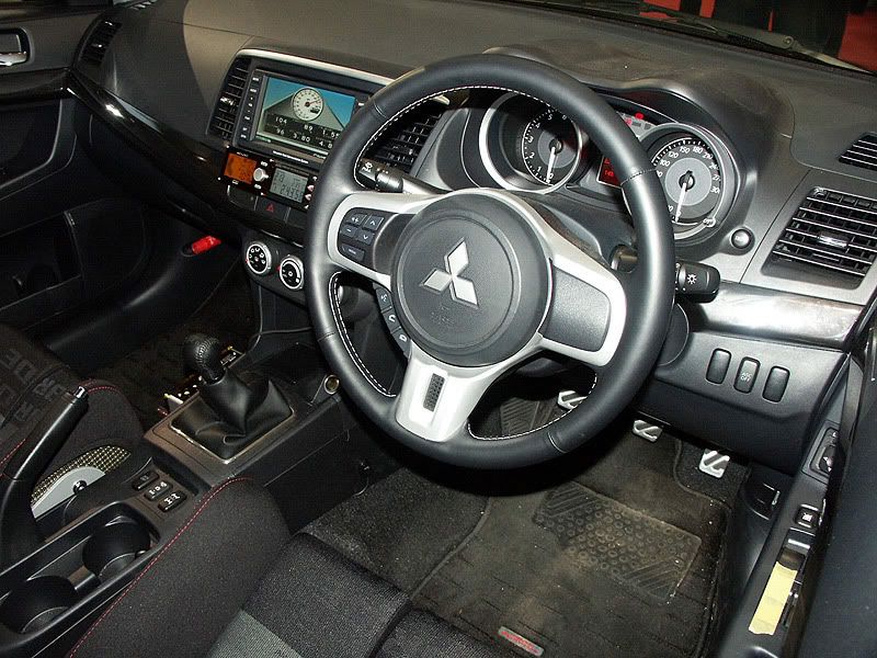
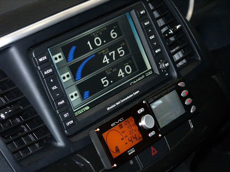
Since someone asked about pictures of the EVC mounted on a Evo X dash, I thought these could be useful:


Sorry, I can't remember where I downloaded these from but since a) it's a RHD car with b) aftermarket seats and c) loaded with HKS stuff I would suspect they were taken at a Japanese tuning show or something. Next to the EVC is the HKS Circuit attack. The integration into Mitsubishi's display screen is due to the CAMP junction box:
http://www.hksusa.com/categories/more.asp?id=1082
I apologise if all the above is old news, I have no experience with the EVC since I've only used AVC-R in the past and spent quite some time trying to find out what was all that in the pics above. In fact, still trying to figure out what 2 of the 3 buttons in the centre console are for...
Last edited by Master Yoda; Apr 2, 2008 at 12:13 PM.


