
Now With Bigger Air Inlet
 Jul 15, 2008, 10:42 AM
#1
Now With Bigger Air Inlet
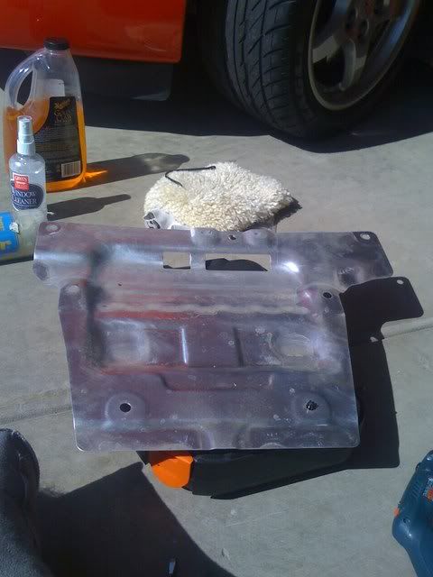
There are somethings I just don't get and one of them is why did  put a small inlet on the naca duct. Theres no reason for them to be small, so I enlarged the inlet. Don't know how much it will help with underhood temps but it's custom so therefore cool!
 So take a look.
Here's the piece of crap stock look
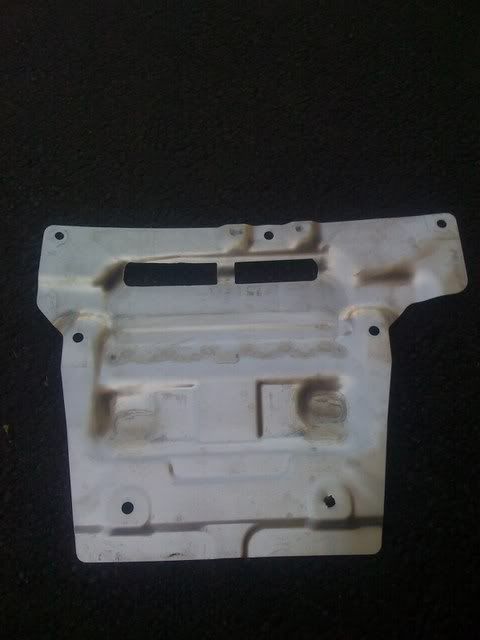
Finished Product
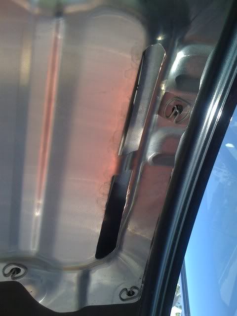
Installed Underhood
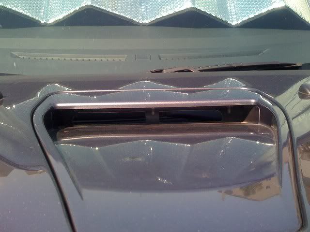
Installed
So take a look.Here's the piece of crap stock look
Finished Product
Installed Underhood
Installed


 Jul 15, 2008, 11:42 AM
#7
With needle nose pilers.
I have my doubts about that. By doing what I did more air will be able to come in. As your driving air is being ramed through it anyways.
I thought about that, but then I saw what it looked like under the shield. It keeps it looking cleaner more organized. So I choose to modify it.
I thought about that, but then I saw what it looked like under the shield. It keeps it looking cleaner more organized. So I choose to modify it.
Trending Topics
Jul 15, 2008, 11:51 AM
#8
I did this as well.. But i took the whole lip out for a bigger inlet. Looks pretty nice with the UICP, also if you take the baking off the small black vents it opens it up huge. I did these and a bunch of other things right away. Factory stuff makes me wonder sometimes.
Edit: Oh and I just took the shield out completely btw. Not sure you need a DIY it's pretty easy.
Edit: Oh and I just took the shield out completely btw. Not sure you need a DIY it's pretty easy.
Last edited by Aseller; Jul 15, 2008 at 11:57 AM.
Jul 15, 2008, 12:05 PM
#9
Newbie

Join Date: Jul 2008
Location: MI
Posts: 14
Likes: 0
Received 0 Likes
on
0 Posts
its a naca duct, what you did was change the entrance width of the duct, i was referring about the part after the opening. the velocity will drop if the area is increased. the only way that would have worked, if you would have made the length along the air flow longer while making the area bigger at the same time.
Jul 15, 2008, 01:32 PM
#10

I've wondered about the vents being so small and covered as well. However, unless any of us are experts in airflow, I don't think we can know the effects of widening that scoop. In all actuality the increase/decrease of airflow through the engine bay due to those vents and the vents behind the wheels is probably fairly minor.
Would be interesting to see this car in a wind tunnel though. I'm betting that the design of the scoops is a certain way for a certain reason and I'm just gonna leave it.
Jul 15, 2008, 02:36 PM
#11
Newbie
Join Date: Jul 2008
Location: MI
Posts: 14
Likes: 0
Received 0 Likes
on
0 Posts
I've wondered about the vents being so small and covered as well. However, unless any of us are experts in airflow, I don't think we can know the effects of widening that scoop. In all actuality the increase/decrease of airflow through the engine bay due to those vents and the vents behind the wheels is probably fairly minor.
Would be interesting to see this car in a wind tunnel though. I'm betting that the design of the scoops is a certain way for a certain reason and I'm just gonna leave it.
Would be interesting to see this car in a wind tunnel though. I'm betting that the design of the scoops is a certain way for a certain reason and I'm just gonna leave it.
 Jul 15, 2008, 07:13 PM
#13
Newbie

Join Date: Jul 2006
Location: Philadelphia
Posts: 88
Likes: 0
Received 0 Likes
on
0 Posts
Fluids 101, flow rate equals cross sectional area * air velocity (Q = AV). Increase the area and the velocity will decrease, raising pressure. Do the opposite by decreasing area, the pressure drops and velocity increases.
Check out Venturi tubes and bernoulli's eq. Same concept here I would bet. Not sure of the impact of the effect here however (agreed I am no expert). I'm sure somewhere in Mitsu there's some CFD analysis done on it.
Check out Venturi tubes and bernoulli's eq. Same concept here I would bet. Not sure of the impact of the effect here however (agreed I am no expert). I'm sure somewhere in Mitsu there's some CFD analysis done on it.
Jul 15, 2008, 11:04 PM
#14
Evolving Member

Join Date: Sep 2007
Location: Over there!
Posts: 209
Likes: 0
Received 0 Likes
on
0 Posts
Ok fluid dynamic engineers...correct me if I am wrong. From what I understand, while the flow rate and cross sectional area/air velocity are proportional, I would guess that the aluminum shield there is partially defeating the purpose of the NACA duct. I mean, the NACA duct is designed in particular proportions to minimize drag from having a cavity in the body yet the BACK of the duct is blocked/partially blocked. Wouldn't this cause a LOT of turbulence at the rear of the duct resulting in LESS laminar air flow? That's GOTTA be a bad thing...but, like I said earlier, I'm no expert...I'm an EE with some Physics background.
verkion
verkion
Jul 16, 2008, 05:26 AM
#15
Newbie
Join Date: Jul 2008
Location: MI
Posts: 14
Likes: 0
Received 0 Likes
on
0 Posts
Ok fluid dynamic engineers...correct me if I am wrong. From what I understand, while the flow rate and cross sectional area/air velocity are proportional, I would guess that the aluminum shield there is partially defeating the purpose of the NACA duct. I mean, the NACA duct is designed in particular proportions to minimize drag from having a cavity in the body yet the BACK of the duct is blocked/partially blocked. Wouldn't this cause a LOT of turbulence at the rear of the duct resulting in LESS laminar air flow? That's GOTTA be a bad thing...but, like I said earlier, I'm no expert...I'm an EE with some Physics background.
verkion
verkion
Like you said its propotional in a straight pipe in a naca ducts things are diferent, it becomes a fuction of depth angle, length, cross sectional area. the only thing that was changed here is the cross sectional area. naca ducts are all designed in a certian way with respect to depth angle and cross sec area. if the cross sec area is increased vel drops and so does laminar flow. high velocities result in higher momentum and that results in higher laminar diffusion. but that does not even matter the kind of modification that was done, i highly doubt one would be able to tell the difference. since ur an ee stick to wires