When you click on links to various merchants on this site and make a purchase, this can result in this site earning a commission. Affiliate programs and affiliations include, but are not limited to, the eBay Partner Network.
So now we're more or less limited up front?. Looks like I could fit an 11.5" wheel with a +30ish offset? Spring perch allowing ,of course.
I need to make a wheel/offset tool that mounts to my car and gives me real-world numbers.
So this is going to let me, with a little other work, get the 18x12 +32 with 315s in there. I dont know how hard its going to be once I put the 335s ons. I'll have to get a little creative on the inside but I have a plan.
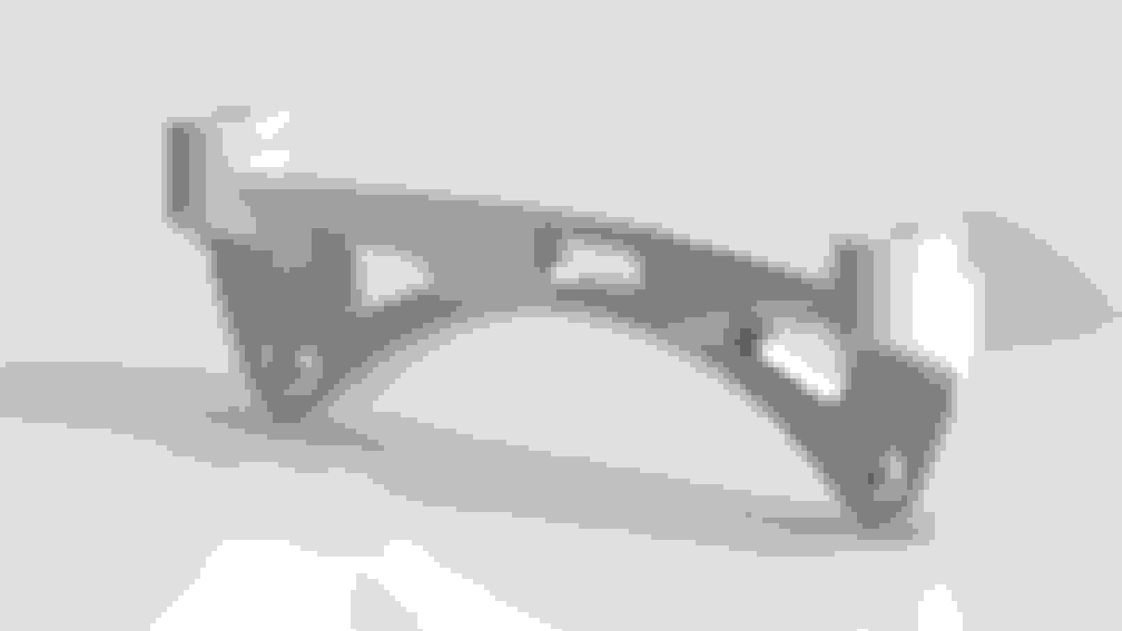
So I had a request to make a brake caliper mount bracket for the Aero6 for a certain someones car and wanted to do something more interesting than just the same ol' boring basic bracket. I know itll take more machine time, but once programmed we're probably talking less than 10min difference to machine it.
This shape came out of doing solidworks topology studies and figuring out from a maximum material condition what can cut away and what is critical. Need to do a little more evaluation but I'm pretty happy with the way way it turned out. I'll probably try to get a set machined next week to go out for anodizing with my next batch of parts.
Looks awesome! I thought you were just doing the aero as a revision to your uprights but that looks like its designed to bolt up to a stock knuckle. What size rotors will be used in conjunction with that? Keep the good stuff coming Dallas!
Not to question solidworks but....are there any radial mounts out there that have holes in them? I have to think that most if not all of the radial mounts made by the ones doing it for many years would have also done this to save weight unless there was a strength/twist issue? Or you think it's purely not profitable in mass so they stuck to solid ones.
So this is going to let me, with a little other work, get the 18x12 +32 with 315s in there. I dont know how hard its going to be once I put the 335s ons. I'll have to get a little creative on the inside but I have a plan.
What is your scrub radius going to be like on this setup?
Originally Posted by Dallas J
So I had a request to make a brake caliper mount bracket for the Aero6 for a certain someones car and wanted to do something more interesting than just the same ol' boring basic bracket. I know itll take more machine time, but once programmed we're probably talking less than 10min difference to machine it.
This shape came out of doing solidworks topology studies and figuring out from a maximum material condition what can cut away and what is critical. Need to do a little more evaluation but I'm pretty happy with the way way it turned out. I'll probably try to get a set machined next week to go out for anodizing with my next batch of parts.
Aero6 brake caliper bracket
Fancy making me some for my AP calipers to suit OE Evo X rotors? I can email you the technical drawing of the caliper.
Not to question solidworks but....are there any radial mounts out there that have holes in them? I have to think that most if not all of the radial mounts made by the ones doing it for many years would have also done this to save weight unless there was a strength/twist issue? Or you think it's purely not profitable in mass so they stuck to solid ones.
I'd put money on there just haven't been a ton of development in optimizing such a thing since theirs very little value in it. A 3D shape is expensive to someone like wilwood to machine but for someone like myself its an opportunity to differentiate with proper design. Another aspect is these tools didnt exist in standard CAD packages 5 years ago. They existed in special programs but the people who understand them dont work for companies that make basic kits. And if they do, they arent in the bracket group
Topology analysis let you specify a maximum material condition and set fixture and load cases. Then to describe it simply, removes material in order of the least important to most important. While its true, as you remove material you are weakening the part, you started with excessive material that you wouldn't have had in the a basic design. It also come out that its not always as intuitive as to where the best places to remove material are. But in general, removing holes in the middle of a box has less impact on its structure than making the box smaller. So thats sorta what you're seeing the results of here.
Originally Posted by TimC909
What is your scrub radius going to be like on this setup?
Fancy making me some for my AP calipers to suit OE Evo X rotors? I can email you the technical drawing of the caliper.
Scrub is really low with the long arms, but SAI is really high. Its basically a tradeoff in my case and I'll have to test both ways to see which is faster.
If you send me the drawings I can let you know if its feasible. Hard part for me is that it'd definitely be a 1-off thing unless others chime in about needing it.
One of the things I have been trying to decide on these is the bolt approach. I don't really want to do threads in aluminum for this. So I was thinking a time-sert from the opposite side. Would be a solid steel thread to pull on that's fixed in the bracket and be much more durable long term.
The loading I'm designing around is an offset (center of rotor position) 7500lbs braking load. I get that based on assuming rotor/tire diameters, 2g braking, 75% loading on front of the car with 75% of that taken by one side. Obviously Im not a bit brake shop with tribal knowledge so I had to create a scenario that seemed excessive. I did the same on the Porsche brake hat I made and its survived a 24h (2 x 12h really) race so far.


 Nov 30, 2018, 08:35 AM