When you click on links to various merchants on this site and make a purchase, this can result in this site earning a commission. Affiliate programs and affiliations include, but are not limited to, the eBay Partner Network.
rustykan's Evo 9 Instructional Build Guide — One Step at a Time
This thread will document all the changes I make to my car, my personal thoughts on each change, and explanations of how I install each part. I am a complete beginner with minimal knowledge and zero experience. I am creating this thread to serve as a resource for anyone else who is also a complete beginner. If I find that installing/swapping out a certain part is particularly complicated for me I will create a separate how-to thread explaining how to install that particular part.
I own an Evo 9 MR SE. When I purchased my Evo, the only modification it came with was an aftermarket K&N Typhoon intake.
Changes I have made to the car:
1. Binary Engineering seat lowering brackets
I replaced my driver's seat's factory seat brackets with lowered aftermarket brackets from Binary Engineering because I needed more leg room. I preferred the stock seating position to the new lowered seating position because the stock seating position had better visibility.
The seat is held in place by one bolt on each bottom corner of the seat. I had to be very careful when removing the seat, as the seat was heavy and the rails were sharp and could easily scratch the car. The stock brackets were secured to the seat rails using blue Loctite and required a large breaker bar to remove.
2. JDM rear bumper
I prefer the sleeker, more aggressive look of the JDM rear bumper to the bulbous USDM rear bumper, so I swapped mine out. JDM rear bumpers were discontinued for a few weeks this past summer (July 2022), and I worried that I had forever lost the opportunity to acquire a JDM rear bumper. When my local dealership notified me that they were back in production, I jumped on the opportunity to buy one.
EDIT – Mitsubishi produces parts in batches. About a month after the local dealership told me the JDM bumper had been discontinued, the dealership's parts department reached out to me and informed me that Mitsubishi was taking orders for an upcoming batch of JDM bumpers they were producing. I paid the dealership in August, and the bumper was delivered to the dealership in November. I do not know how to keep up-to-date with what parts Mitsubishi periodically produces in batches. As I understand, these parts are marked as discontinued in dealership inventory until Mitsubishi Japan opens up the ordering books.
Swapping out the rear bumper was a more complicated process than I had anticipated. I created a how-to thread detailing the process in its entirety. Link to separate thread
.
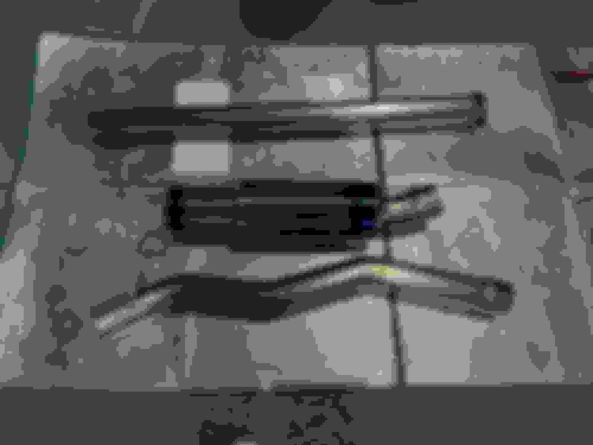
3. Tomei Expreme Ti exhaust (part number TB6090-MT01A)
The stock exhaust is supported by two hangers on the downpipe and three hangers around the muffler. There are two studs and nuts connecting the catalytic convertor to the cat back, and three bolts connecting the cat back to the muffler. To remove the cat back, unscrew the two nuts connecting the cat back to the catalytic convertor and then push the three hangers supporting the muffler out of their rubber mounts. This allows the cat back and muffler to be removed as one piece. I used rubber hanger removal pliers and windex to remove the exhaust hangers from their rubber mounts. The nuts on the catalytic convertor flange were thoroughly rusted. They had to be heated up using MAPP gas until glowing bright red, left to cool, then sprayed with WD-40 rust penetrant. The wire for the oxygen sensor is secured along the top side of the exhaust, so that was first unclipped from the exhaust and moved out of the way. After that, I stuffed a kevlar blanket between the exhaust pipe and the car to prevent the heat of the torch from affecting anything besides the nuts. After the nuts were sprayed with rust penetrant, I hammered on bolt extractor sockets onto the nuts and used a massive breaker bar to break them free.
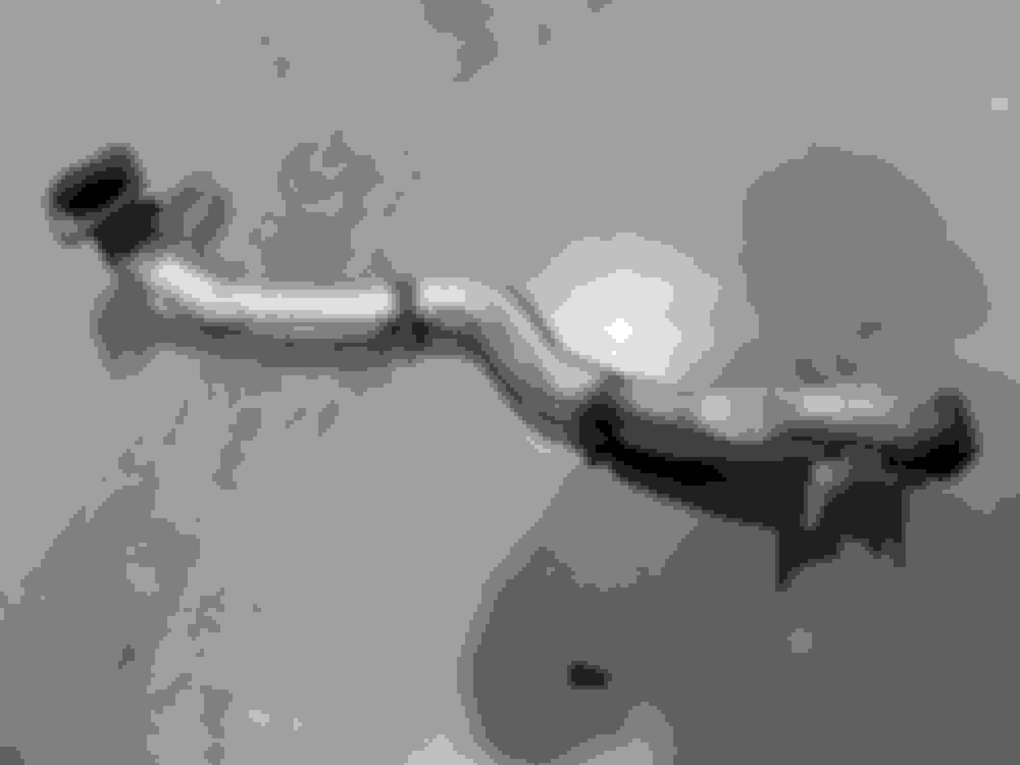
My stock exhaust was in poor condition. I want to retain factory components I remove from the car, but my stock exhaust was too far gone. Unfortunately, the stock exhaust is also discontinued. I decided to save the muffler by cutting the exhaust near the muffler with a Sawzall and throwing away the rest of the exhaust. In the future if I want to put the stock muffler back on the car I can have an exhaust shop fabricate a new cat back that uses the factory muffler.
I debated whether or not to remove the blue coloring from the exhaust tip, but decided against doing so as the blue exhaust matches my blue paint. If my car wasn't blue I probably would have removed the blueing on the exhaust. I really like the quality of the Tomei exhaust. All of the welds are entirely uniform (I'm guessing the welds are made by a machine EDIT – I watched a video of an exhaust being welded in which the piping was held by a fixture that spun the piping, allowing the welding torch to be held in place and produce a perfectly seamless weld. My guess is that this exhaust was welded in the same manner), there are no markings or any damage on the exhaust, and every edge of the piping and flanges is smooth to the touch (nothing is sharp). The Tomei exhaust is significantly lighter than the stock exhaust. The Tomei is also much much louder than the stock exhaust. With the stock exhaust, I could not hear the exhaust when driving at low RPMs. Instead, I would only hear various whines from the engine bay and outside road noise. Now, all I hear at all times is the exhaust. The exhaust sound changes noticeably as engine RPM increases. I really like how the exhaust sounds at high RPM (above 4k RPM).
I like the way the car sounds from the outside, but I do not like the way the car sounds from the inside. I miss the relatively quiet interior sound level the car had with the stock exhaust. I will be looking into applying some kind of sound deadening to the bare metal underneath the trunk carpet to hopefully prevent some of the exhaust sound from entering the cabin.
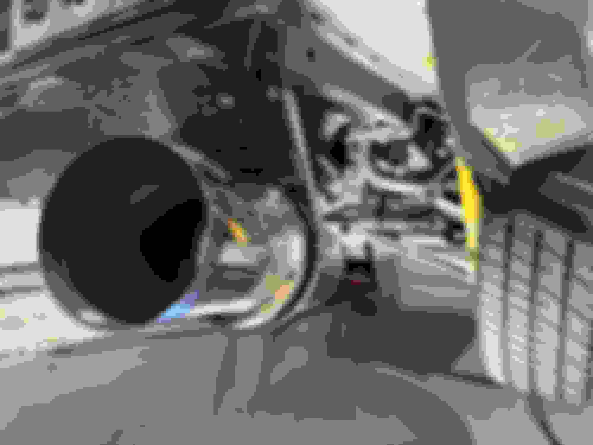
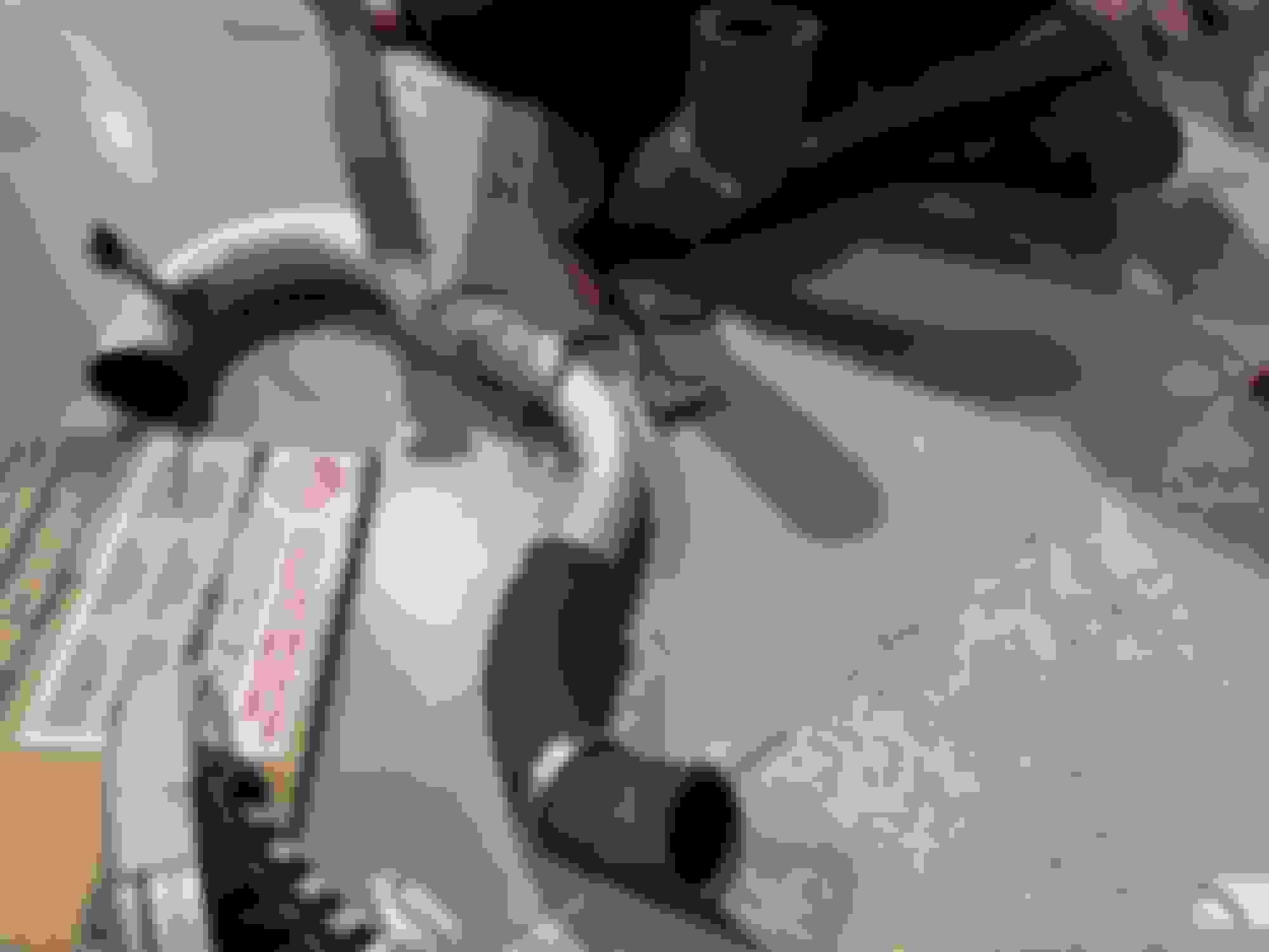
4. ETS LP2 lower intercooler pipe
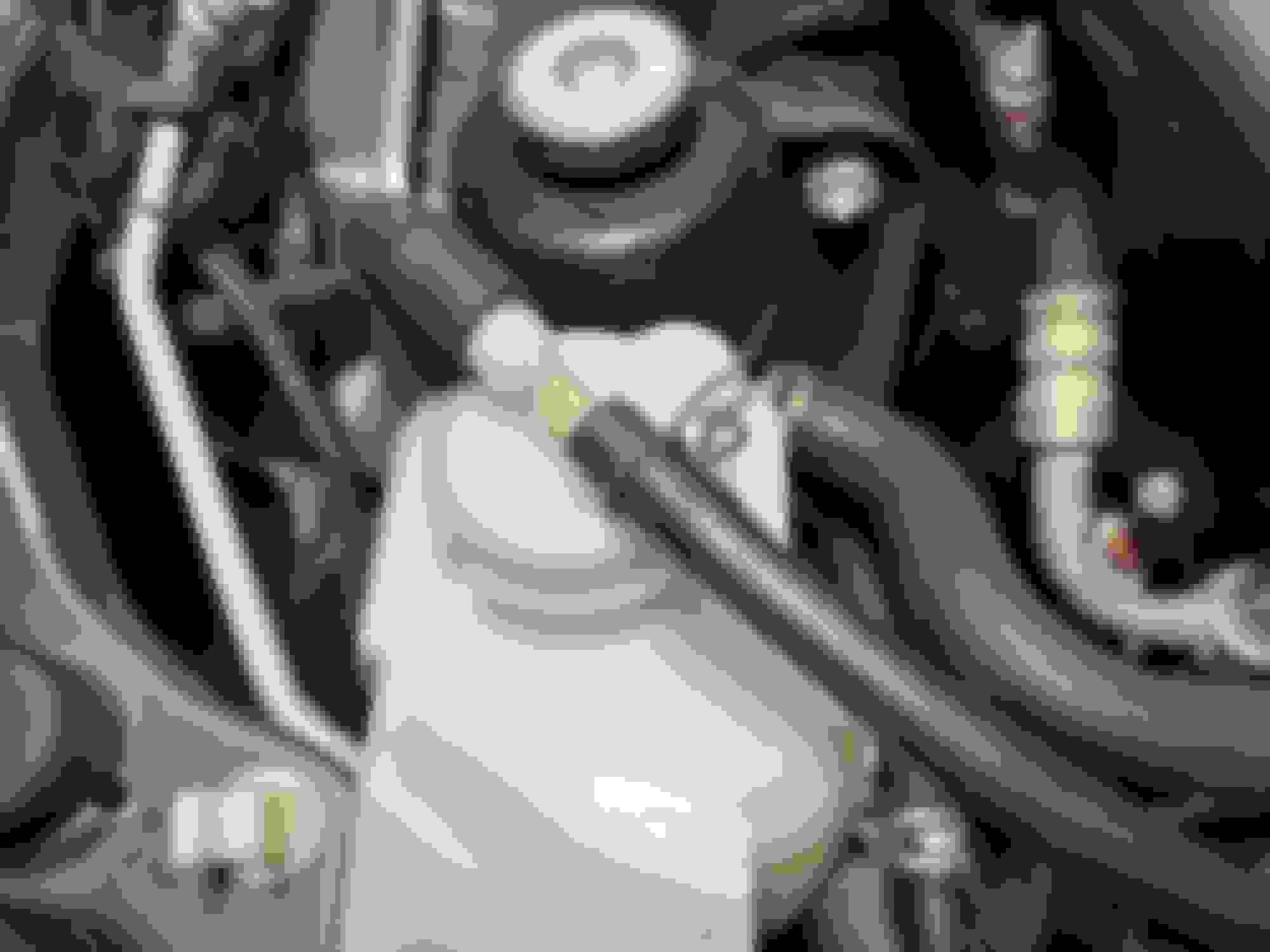
I have read forum posts and watched YouTube videos discussing the benefits of replacing this piece. The stock lower intercooler pipe (LICP) has multiple bends and necks down in the middle to a much smaller diameter. The stock LICP also makes use of a long flexible coupler that connects the LICP to the turbo compressor outlet. The idea behind replacing this piece is to improve airflow by eliminating the unnecessary bends, removing the neck down, and eliminating the long flexible coupler. I have read that the flexible coupler expands during boost and leads to a "squishier" pedal feel.
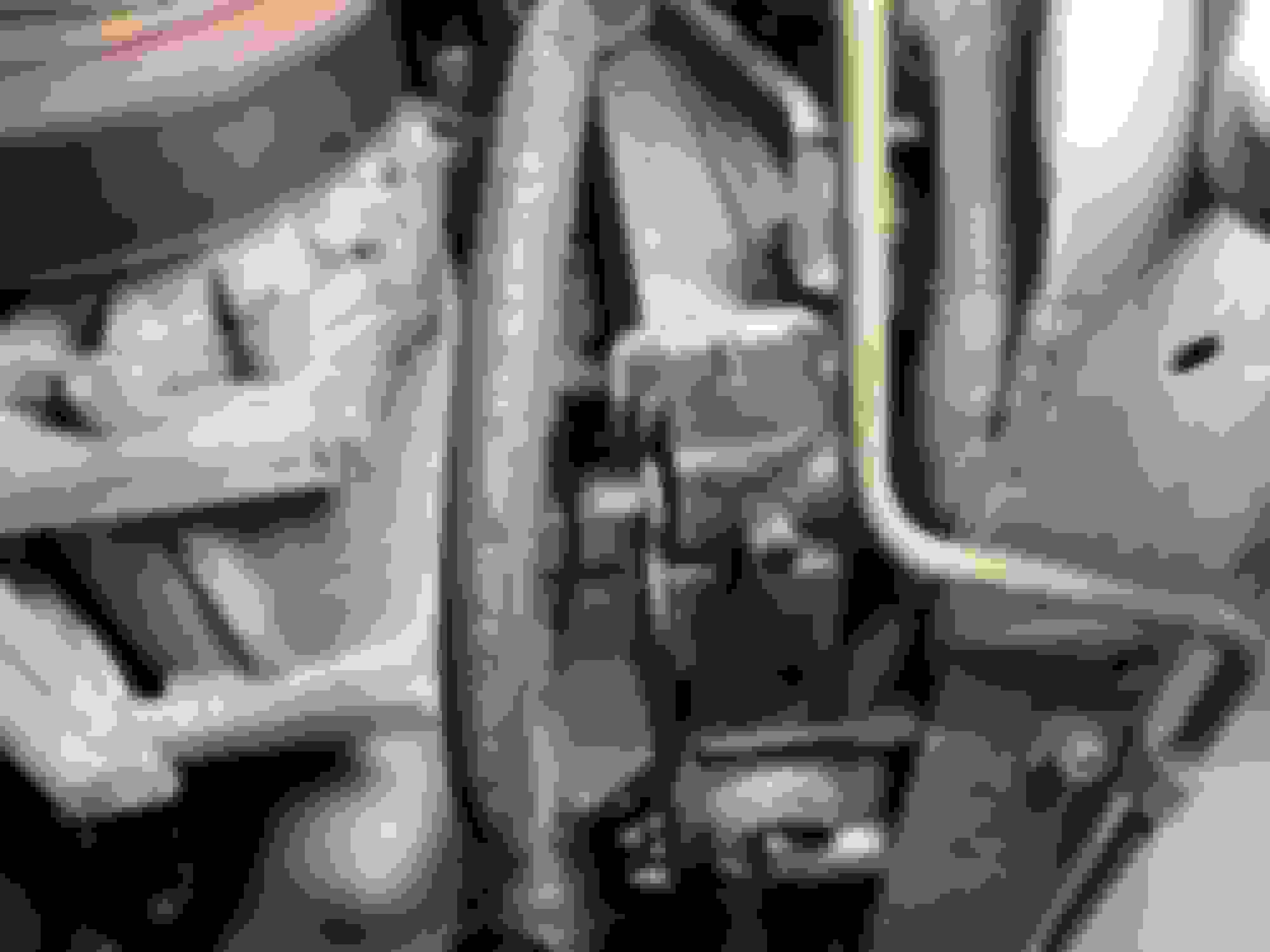
The LICP is hidden behind the bottom of the passenger's side of the front bumper. The LICP can be replaced without removing the front bumper. First, remove the front undertray. The undertray is held in place by many plastic clips and a few screws. The undertray is made of three pieces, of which only the middle and passenger's side pieces have to be removed to access the LICP. The stock LICP has two arms that extend upwards towards the engine bay and bolt to the car. One arm is significantly longer than the other. The longer arm's bolt is very difficult to reach. This bolt may be easier to reach if the front bumper is removed, but I did not remove my front bumper to test this. The ETS LICP does not mount directly to the car like the stock LICP. The ETS LICP is only connected by the two couplers on each end. The ETS LICP fits in the factory location and does not get in the way of reinstalling the undertray.
The ETS LICP comes with one coupler to replace the long flexible coupler connecting the LICP to the turbo compressor outlet, and reuses the stock coupler connecting the LICP to the intercooler. The ETS LICP is noticeably heavier than the stock LICP. I am honestly unsure if driving the car feels any different with this new LICP compared to the stock piece. I swapped out the exhaust and the LICP at the same time, so I wasn't able to test the LICP on its own. If I had tested the LICP alone, perhaps I would have been able to say more definitively whether or not it makes a noticeable difference. With that being said, the reasoning behind replacing the LICP seems to make sense so I don't regret buying and installing this part.
These are all of the changes I have made to my car so far. My car is currently untuned. I will not be able to have the car tuned for a bit so I decided to put on parts that can be ran without a tune. I have more parts in hand but do not currently have the time to install them. The parts I own but have not yet installed are as follows:
ETS 3.5" wide tank intercooler
MAPerformance recirculated O2 eliminator downpipe
Injector Dynamics 1050x injectors
Deatschwerks 340lph fuel pump
Grimmspeed electronic boost control solenoid
AEM X-series inline wideband controller
All of these parts should be drop-in replacements that do not require any modification of existing components. I chose these parts because I want to retain the stock clutch and I believe the stock clutch is able to handle whatever power the car produces with these parts. The car will be tuned on 93.
To be continued...
Last edited by rustykan; Apr 20, 2024 at 01:43 PM.
This thread will document all the changes I make to my car, my personal thoughts on each change, and explanations on how to change each part. I am a complete beginner with minimal knowledge and zero experience. I am creating this thread to serve as a resource for anyone else who is also a complete beginner. If I find that swapping out a certain part is rather complicated I will create a separate how-to thread explaining how to install that particular part.
I own an Evo 9 MR SE. This car is my daily driver, so all the modifications I make will be basic and "daily friendly". When I purchased my Evo, the only modification it came with was an aftermarket K&N Typhoon intake.
Changes I have made to the car:
1. Binary Engineering seat lowering brackets
I replaced my driver's seat's factory seat brackets with lowered aftermarket brackets from Binary Engineering because I needed more leg room. I actually preferred the stock seating position to the new lowered seating position because the stock seating position had better visibility.
The seat is held in place by one bolt on each corner of the seat. I had to be very careful when removing the seat, as the seat was heavy and the rails were sharp and could easily scratch the car. The stock brackets were secured to the seat rails using blue Loctite and required a large breaker bar to remove.
2. JDM rear bumper
I prefer the sleeker, more aggressive look of the JDM rear bumper to the bulbous USDM rear bumper, so I swapped mine out. JDM rear bumpers were discontinued for a few weeks this past summer, and I worried that I had forever lost the opportunity to acquire a JDM rear bumper. When my local dealership notified me that they were back in production, I jumped on the opportunity to buy one.
Swapping out this bumper was a more complicated process than I had anticipated. I created a separate how-to thread detailing the process in its entirety.
3. Tomei Expreme Ti cat back exhaust
This was my first time being underneath a car. The stock exhaust is supported by two hangers on either side of the catalytic convertor and three hangers supporting the muffler. There are two studs and nuts connecting the catalytic convertor to the cat back, and three bolts connecting the cat back to the muffler. To remove the cat back, unscrew the two nuts connecting the cat back to the catalytic convertor and then push the three hangers out of their rubber mounts. This allows the cat back and muffler to be removed as one piece. I used rubber hanger removal pliers and windex to remove the exhaust hangers from their rubber mounts. The nuts on the catalytic convertor flange were incredibly rusted. They had to be heated up using MAPP gas until glowing bright red, left to cool, then sprayed with WD-40 rust penetrant. The wire for the oxygen sensor is secured along the top side of the exhaust, so that was first unclipped from the exhaust and moved out of the way. After that, I stuffed a kevlar blanket between the exhaust pipe and the car to prevent the heat of the torch from affecting anything besides the nuts. After the nuts were sprayed with rust penetrant, I hammered on bolt extractor sockets onto the nuts and used a massive breaker bar to break them free.
My stock exhaust was disgusting. I want to retain the factory components I remove from the car, but my stock exhaust was too far gone. Unfortunately, the stock exhaust is also discontinued. I decided to save the muffler by cutting the exhaust near the muffler with a Sawzall and throwing away the rest of the exhaust. In the future I can have an exhaust shop fabricate a new cat back that uses the factory muffler.
I was debating whether or not I should remove the blue color from the exhaust, but decided against doing so as the blue exhaust matches my blue paint. If my car wasn't blue I probably would have remove the blueing on the exhaust. I really like the quality of the Tomei exhaust. All of the welds are entirely uniform (I'm guessing the welds are made by a machine), there are no markings or areas of damage on the exhaust, and all of the edges on the exhaust pipes and flanges are smooth to the touch (nothing is sharp). The Tomei exhaust is significantly lighter than the stock exhaust. The Tomei is also much much louder than the stock exhaust. With the stock exhaust, I could not hear the exhaust when driving at low RPMs. Instead, I would only hear various whines from the engine bay and outside road noise. Now, all I hear at all times is the exhaust. The exhaust sound changes noticeably as engine RPM increases. I really like how the exhaust sounds at high RPM (above 4k RPM).
I like the way the car sounds from the outside, but I do not like the way the car sounds from the inside. I miss the relatively quiet interior sound level the car had with the stock exhaust. I will be looking into applying some kind of sound deadening to the bare metal underneath the trunk carpet to hopefully prevent some of the exhaust sound from entering the cabin.
4. ETS LP2 lower intercooler pipe
I have read forum posts and watched YouTube videos discussing the benefits of replacing this piece. The stock lower intercooler pipe (LICP) has multiple bends and necks down in the middle to a much smaller diameter. The stock LICP also makes use of a long flexible coupler that connects the LICP to the turbo compressor outlet. The idea behind replacing this piece is to improve airflow by eliminating the unnecessary bends, removing the neck down, and eliminating the long flexible coupler. I have read that the flexible coupler expands during boost and leads to a "squishier" pedal feel.
The LICP is hidden behind the bottom of the passenger's side of the front bumper. The LICP can be replaced without removing the front bumper. First, remove the front undertray. The undertray is held in place by many plastic clips and a few screws. The undertray is made of three pieces, of which only the middle and passenger's side pieces have to be removed to access the LICP. The stock LICP has two arms that extend upwards towards the engine bay and bolt to the car. One arm is significantly longer than the other. The longer arm's bolt is very difficult to reach. This bolt may be easier to reach if the front bumper is removed, but I did not remove my front bumper to test this. The ETS LICP does not mount directly to the car like the stock LICP. The ETS LICP is only connected by the two couplers on each end. The ETS LICP fits in the factory location and does not get in the way of reinstalling the undertray.
The ETS LICP comes with one coupler to replace the long flexible coupler connecting the LICP to the turbo compressor outlet, and reuses the stock coupler connecting the LICP to the intercooler. The ETS LICP is noticeably heavier than the stock LICP. I am honestly unsure if driving the car feels any different with this new LICP compared to the stock piece. I swapped out the exhaust and the LICP at the same time, so I wasn't able to test the LICP on its own. If I had tested the LICP alone, perhaps I would have been able to say more definitively whether or not it makes a noticeable difference. With that being said, the reasoning behind replacing the LICP seems to make sense so I don't regret buying and installing this part.
These are all of the changes I have made to my car so far. My car is currently untuned. I will not be able to have the car tuned for a bit so I decided to put on parts that can be ran without a tune. I have more parts in hand but do not currently have the time to install them. The parts I own but have not yet installed are as follows:
ETS 3.5" wide tank intercooler
MAPerformance recirculated O2 eliminator downpipe
Injector Dynamics 1050x injectors
Deatschwerks 340lph fuel pump
Grimmspeed electronic boost control solenoid
AEM X-series inline wideband controller
All of these parts should be drop-in replacements that do not require any modification of existing components. I chose these parts because I want to retain the stock clutch and I believe the stock clutch is able to handle whatever power the car produces with these parts. The car will be tuned on 93.
I also have all of the maintenance items for the 60k service, which I will be doing myself at a later date. I will make a separate instructional how-to for that service in the future.
Finally, I plan on attending my first beginner track day this March. If that happens I will write about my experience in this thread.
Education suffers when schools receive insufficient financing. Hence, funding for this approach is required. Every person should prioritize their education. Also, learning is not a simple process. While I was a student, this website https://www.academicghostwriter.org was helpful. There were many assignments provided to us. And I was able to complete whatever the teacher asked of us because of the service.
To be continued...
Good start. I've gone down a lot of the same route as you with the JDM Rear, ETS IC, ETS Lower IC pipe, Fuel Pump, and Suspension. One thing that I learned the hard way is to make sure that your LICP isn't pushing on your AC line (flexible coming out of compressor going to condenser). If it touches the AC line it will eventually melt a hole in it and then you're looking at having to get a new AC hose and have your system recharged and evacuated. Just carefully bend the hose a little bit at the condenser to space it off the LICP and you should be good, For extra safety you can also put a flexible heat wrap around the AC hose that you can just split down the length and use metal clamps to hold in place: https://www.pegasusautoracing.com/pr...oduct=3299-001
It has been a while and I am finally ready to update my build thread.
Some quick things to note:
I did not install the AEM wideband controller. I still have it, but chose to hold off on the installation for now.
I attended my first ever track day , just not in my Evo .
My rust penetrant of choice is WD-40 Specialist Penetrant.
Now onto the changes I've made –
SOUND DEADENING
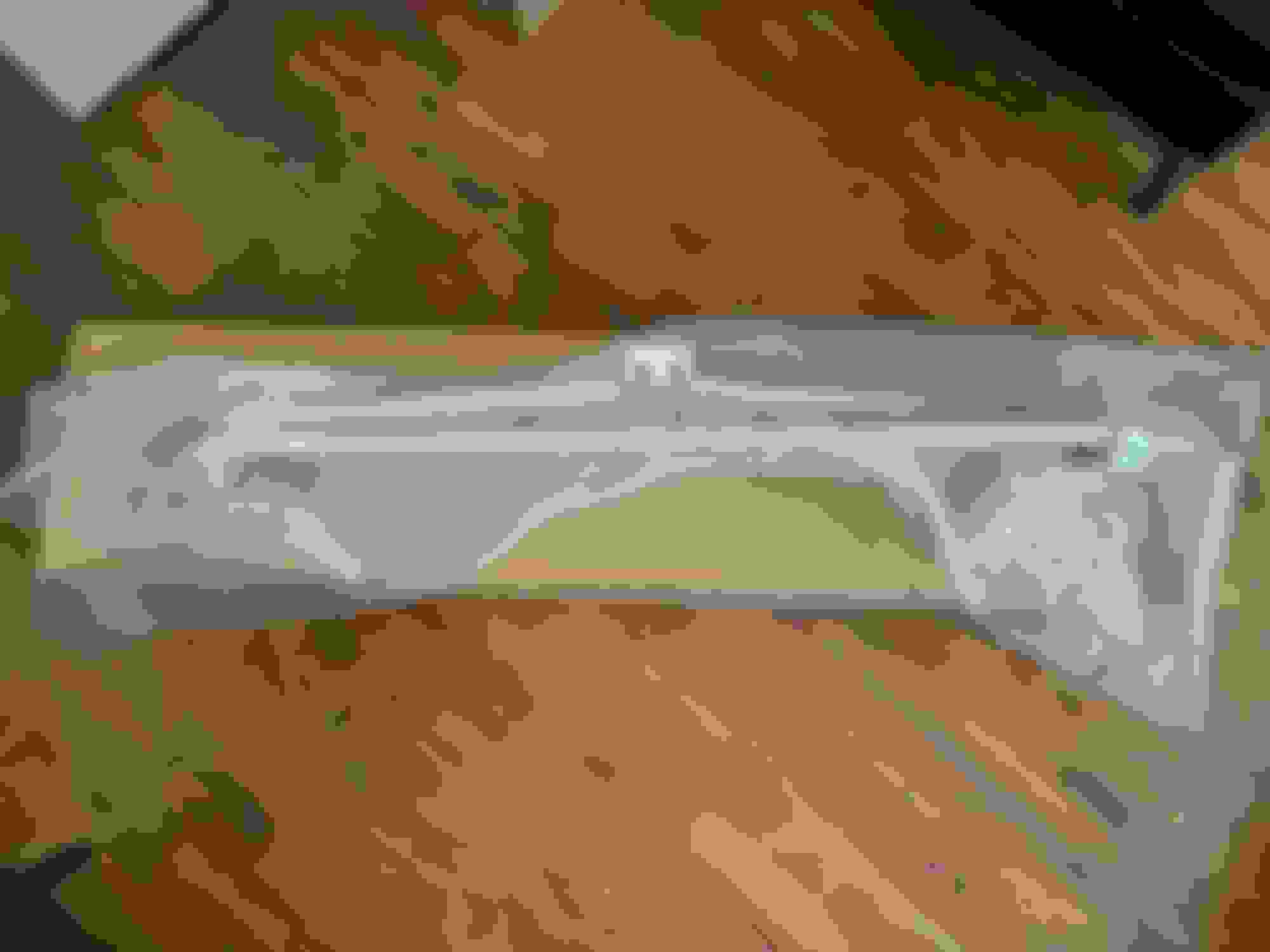
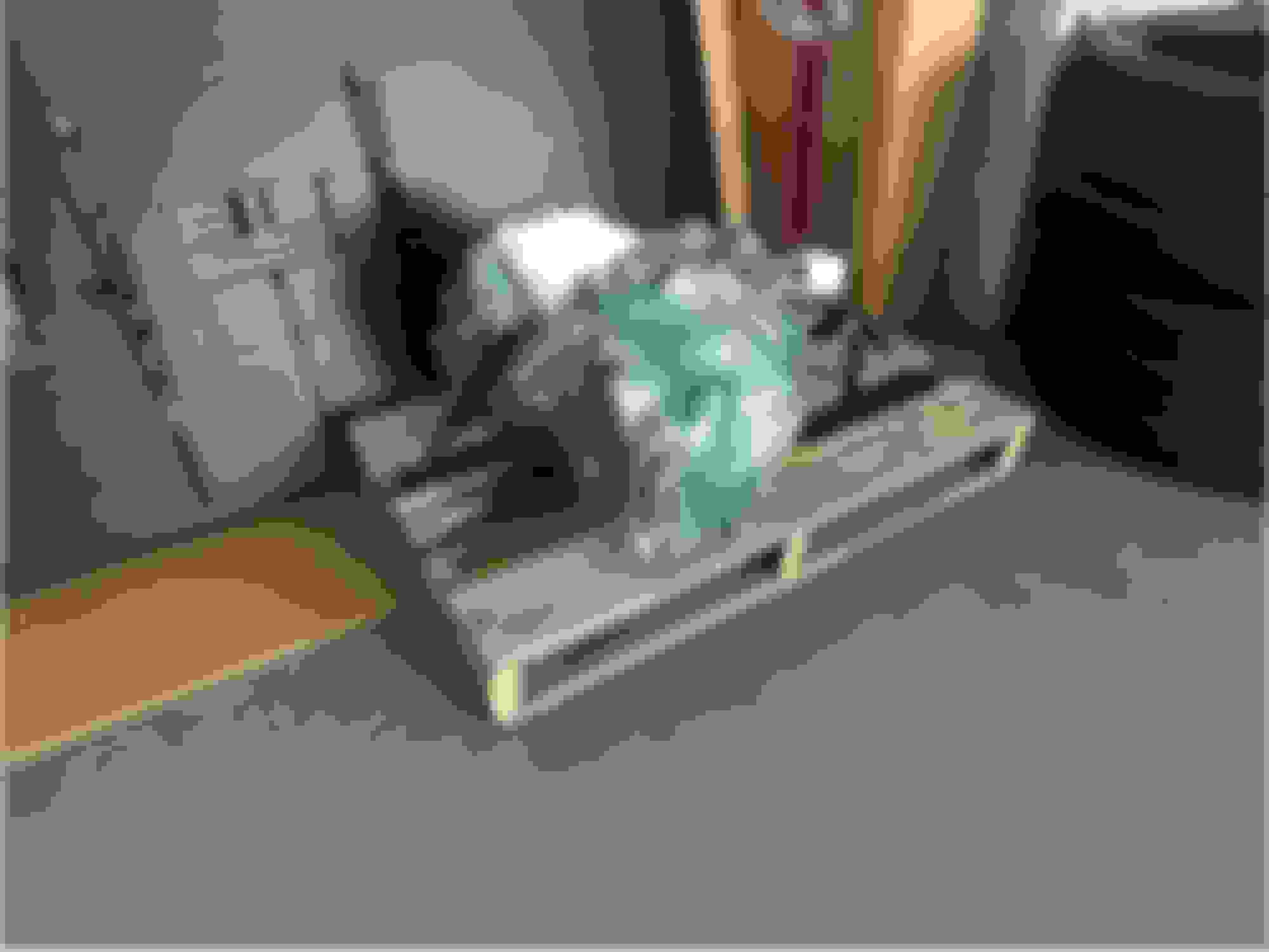
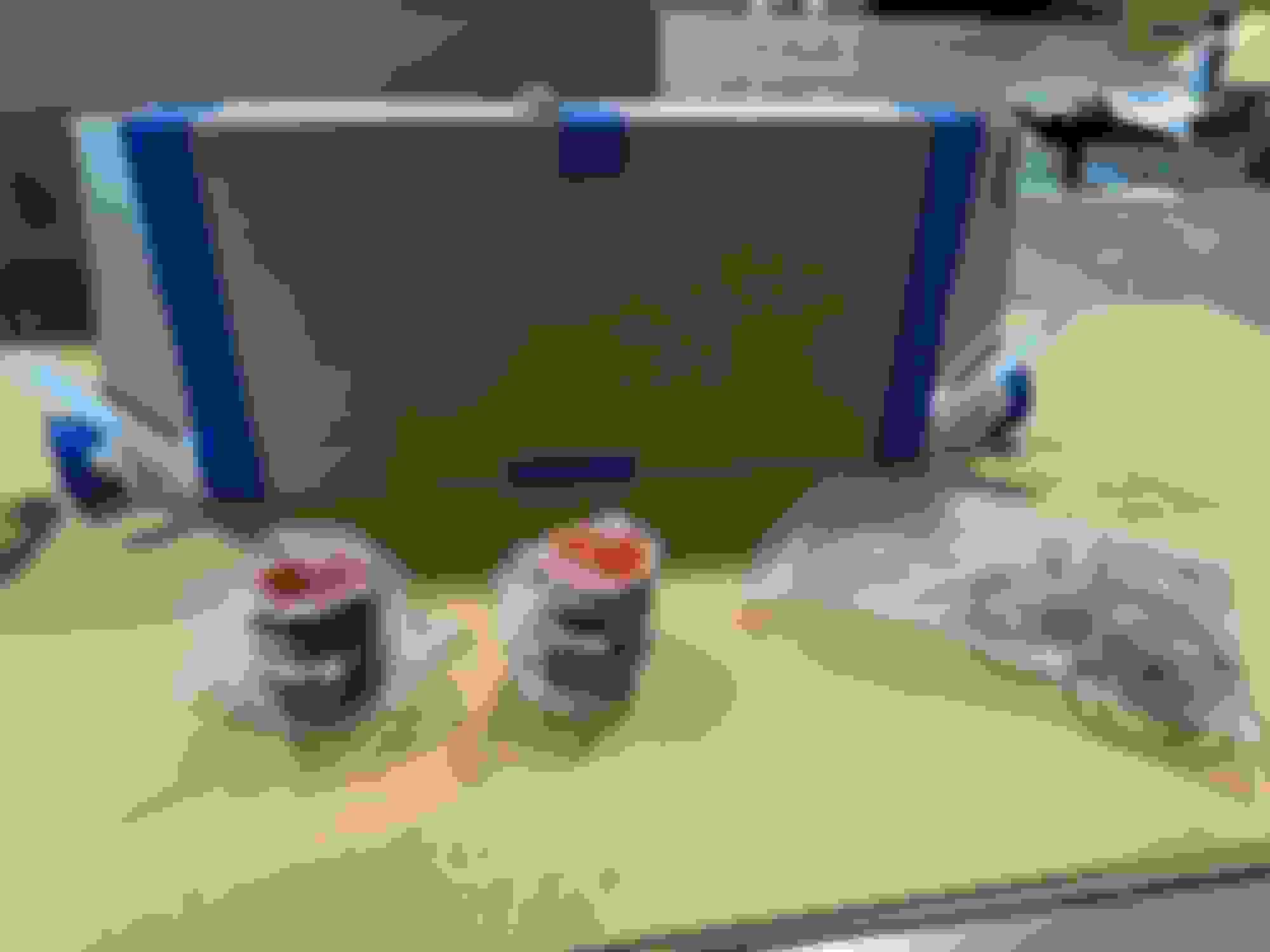
I decided to line my trunk with sound deadening in an attempt to reduce the amount of exhaust sound I hear when driving my car. A company called Kilmat recently released a thicker version of their sound deadening product called Kilmat Extra, which I chose to use. I purchased one box of 25 sheets of Kilmat Extra. I did not weight the sheets but if I had to guess I think I added about 15lbs to my car.
Kilmat Extra is 100mil, the thickest sound deadening I could find
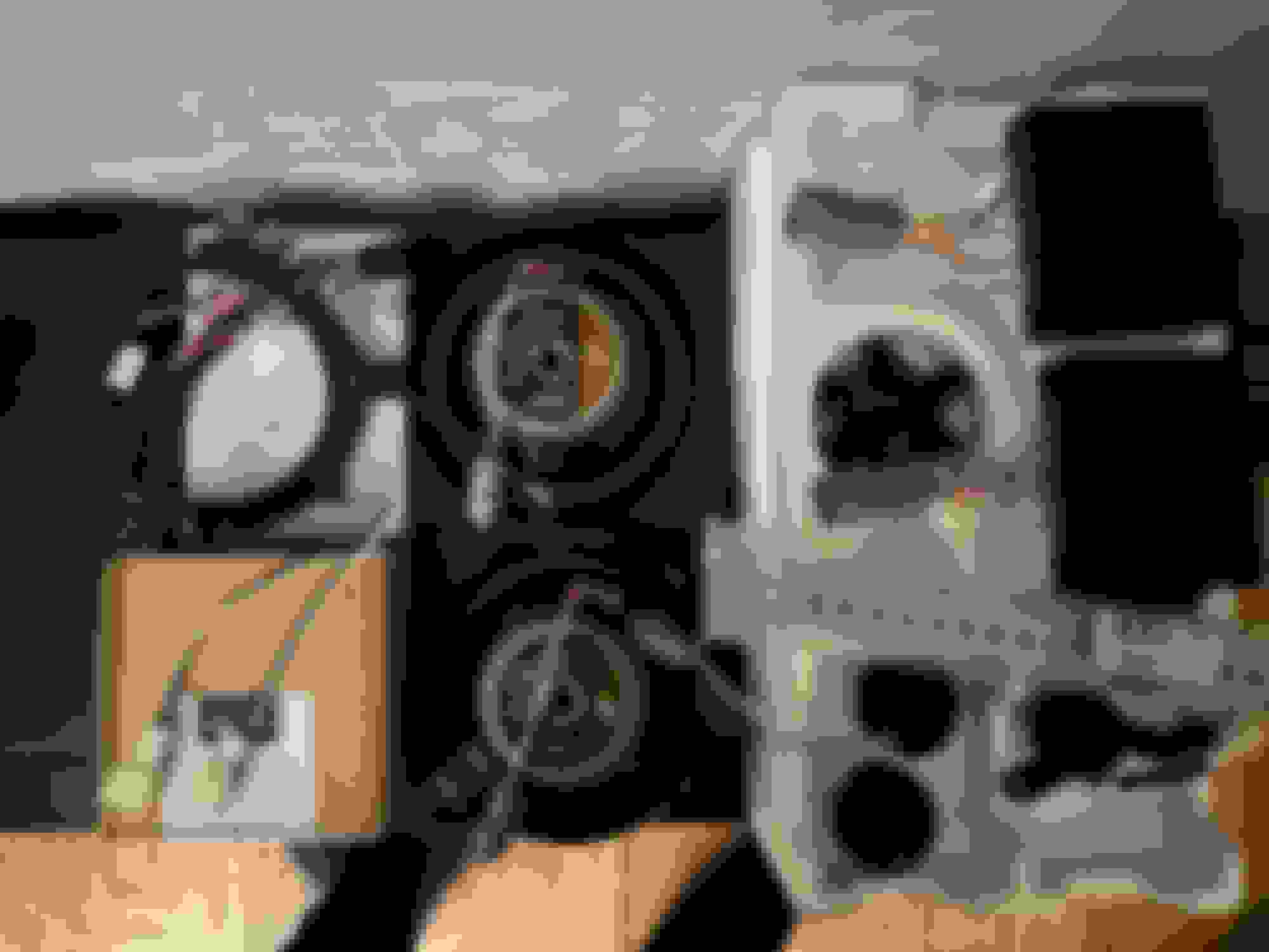
The top side of the Kilmat sheets is covered with foil. Inside of the Kilmat is an odorless black rubber material. The bottom side of the Kilmat is wax paper which is peeled off to reveal adhesive. Applying the Kilmat was straightforward. I stripped my trunk and lined the entire trunk with the Kilmat. I also applied Kilmat inside each of the trunk side compartments but did not take pictures of the compartments. All of the trunk liners fit back in without issue, so it is impossible to visually tell that my trunk is lined.
I continued to apply Kilmat after I took this picture, but it provides an idea of what my trunk looks like now
At first I couldn’t tell if the Kilmat reduced the exhaust sound at all, but after not driving the car for a while and returning to it, I could tell the difference. The difference in exhaust volume level was actually quite notable. I am happy with the results.
SOUND SYSTEM
The stock sound system is awful, so I purchased front and rear replacement speakers. At this time I am not interested in external amplifiers or subwoofers. I chose Infinity Reference REF-6530cx component speakers for the front doors and Infinity Reference REF-6532ex coaxial speakers for the rear deck. My speakers came with wire adapters to make them plug-and-play.
So far, I have only installed the rear speakers. The rear speakers are accessed through the trunk. The only problem with the installation was that the speaker mounting bracket didn’t fit properly into the car. The mounting ring had 3 tabs that I had to cut off in order for the speakers to fit. The new speakers fit under the rear speaker covers.
Mounting ring with three tabs that needed to be cut off
Factory speaker vs Infinity speaker
Metra speaker adapters
The speakers function properly, but I will wait until I have installed the front speakers as well before I give my thoughts on them.
FUEL PUMP
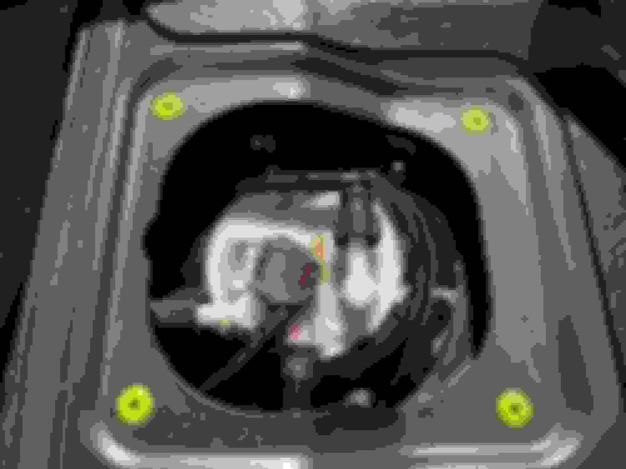
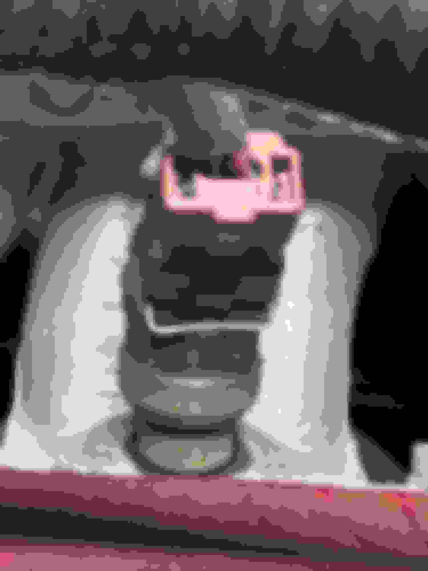
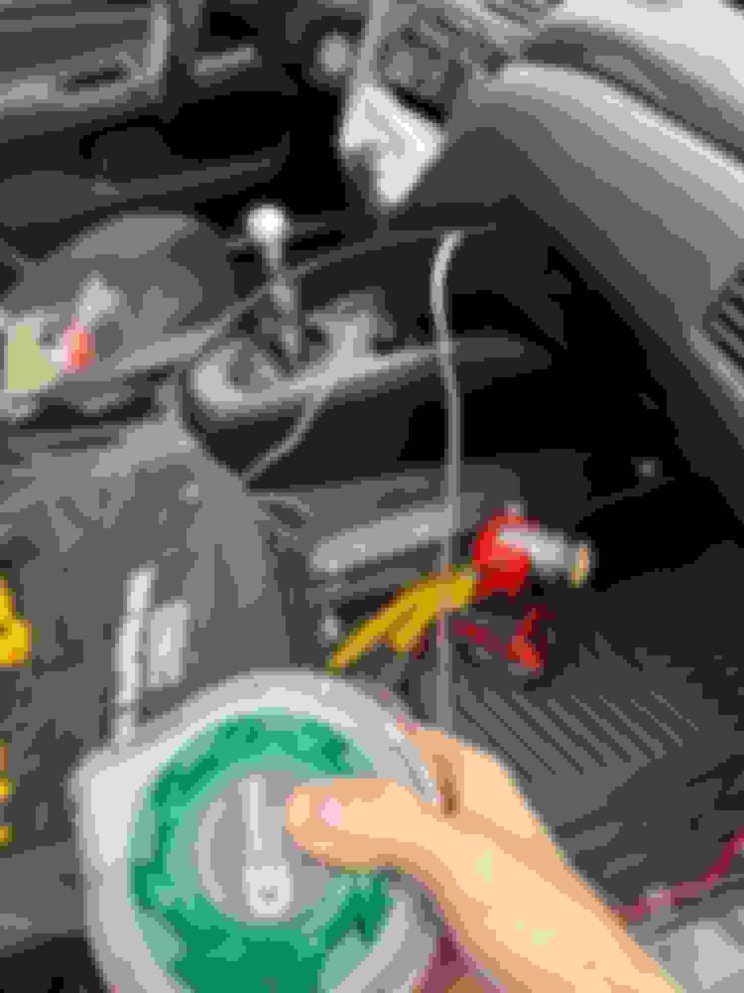
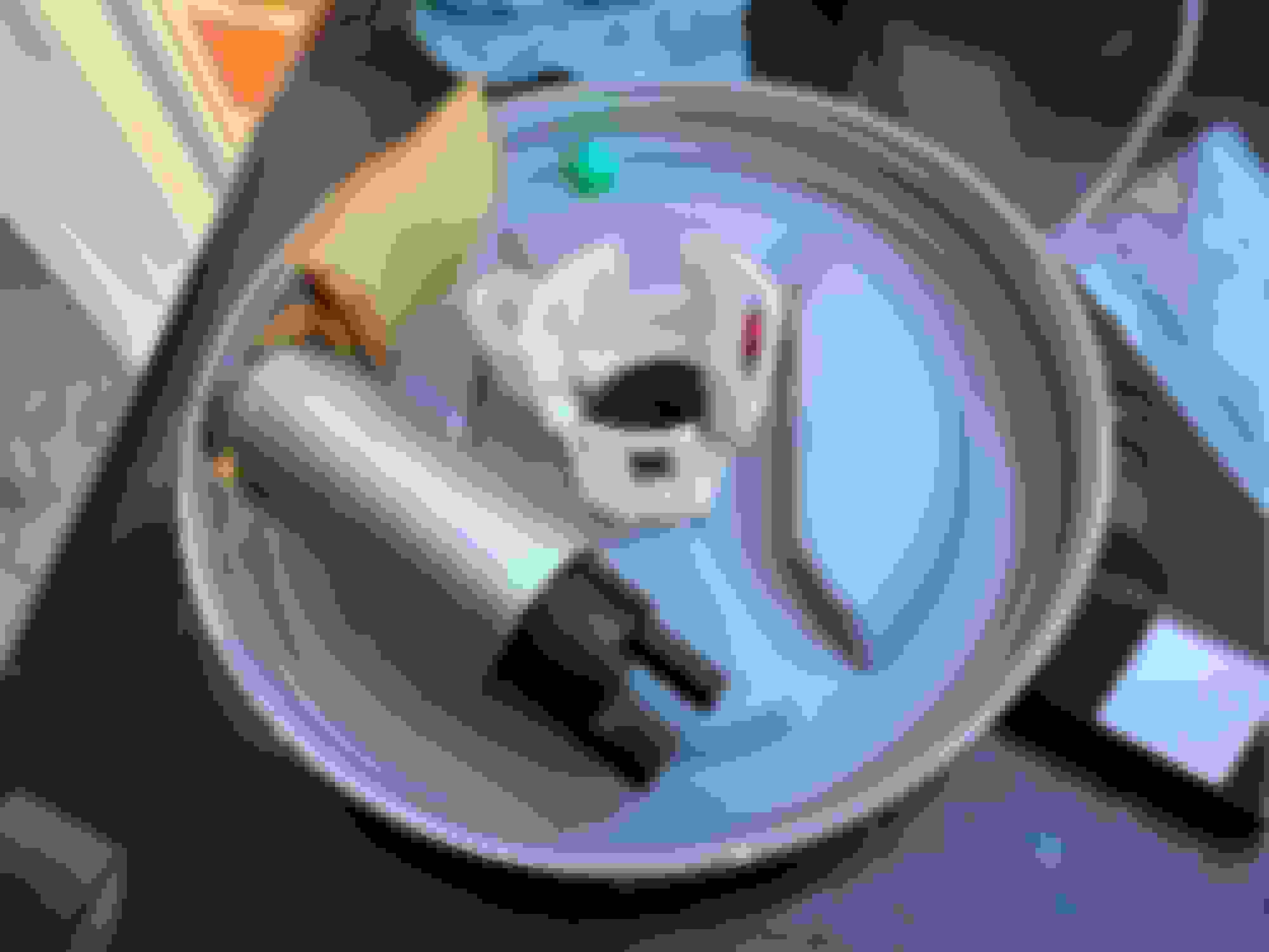
I replaced my stock fuel pump with a Deatschwerks DW300, a 340lph drop-in replacement pump. One reason I chose this pump is because I read that the popular Walbro 255 can produce a whine, whereas this pump is silent. I also believe that this size fuel pump is roughly the biggest that the stock fuel system is capable of handling before electrical or fuel hanger changes need to be made. The fuel tank is located underneath the rear seats. The rear seats have two latches underneath them that need to be pulled before they can be removed. Removing the rear seats reveals two black metal covers. The cover on the driver’s side is where the fuel pump hangar is located. Remove the cover to reveal the top of the fuel tank and the fuel hanger.
Top of the fuel hanger, beneath rear seats
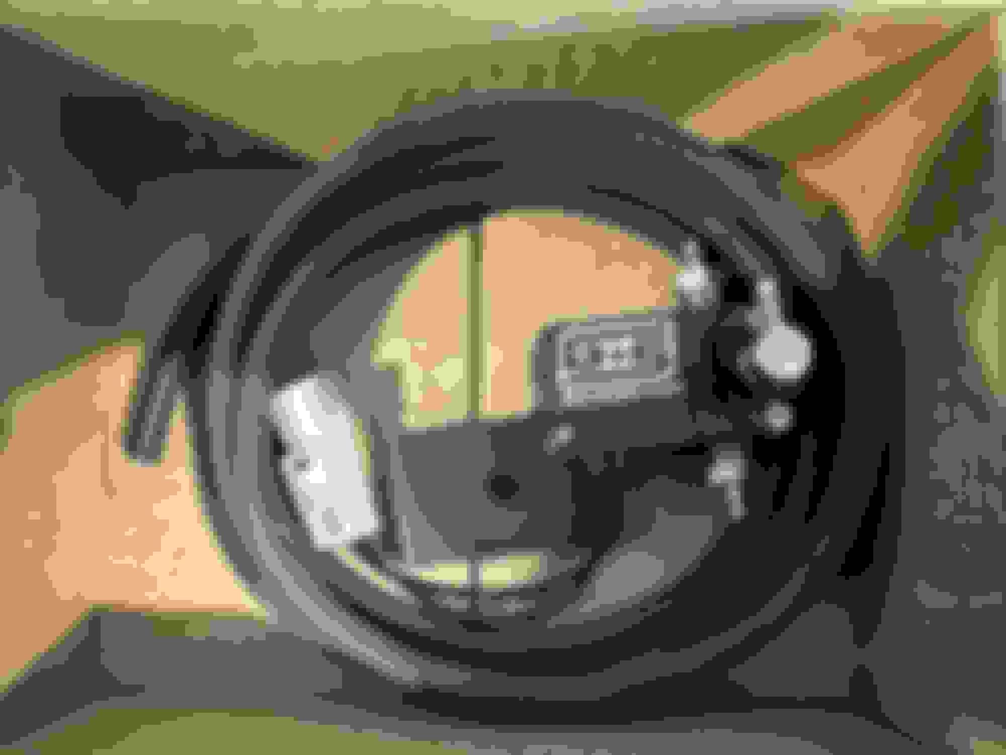
The fuel hanger houses the fuel pump. On top of the fuel hanger is an electrical connector (gray), a fuel sending line (that leads to the engine), a fuel return line (comes from the engine), and a line that connects the driver and passenger sides of the fuel tank. Disconnect the electrical connector and three fuel lines, and the hanger can be removed. Removing the fuel hanger is frustrating. The top of the fuel hanger is larger than the hatch it has to fit through, so the fuel hanger has to be removed by rotating it at an angle. Begin by removing the metal ring around the fuel hanger, then focus on removing the hanger itself. If there is an easy way to remove the fuel hanger I could not figure it out. The fuel hanger will likely be dripping gasoline when it is pulled out of the fuel tank. There will also be gasoline inside of the fuel hanger which will spill out when the factory fuel pump is removed from the hanger.
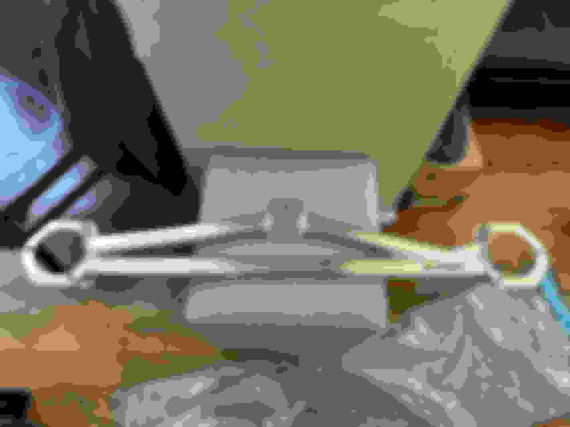
Stock fuel pump with sock removed from hanger
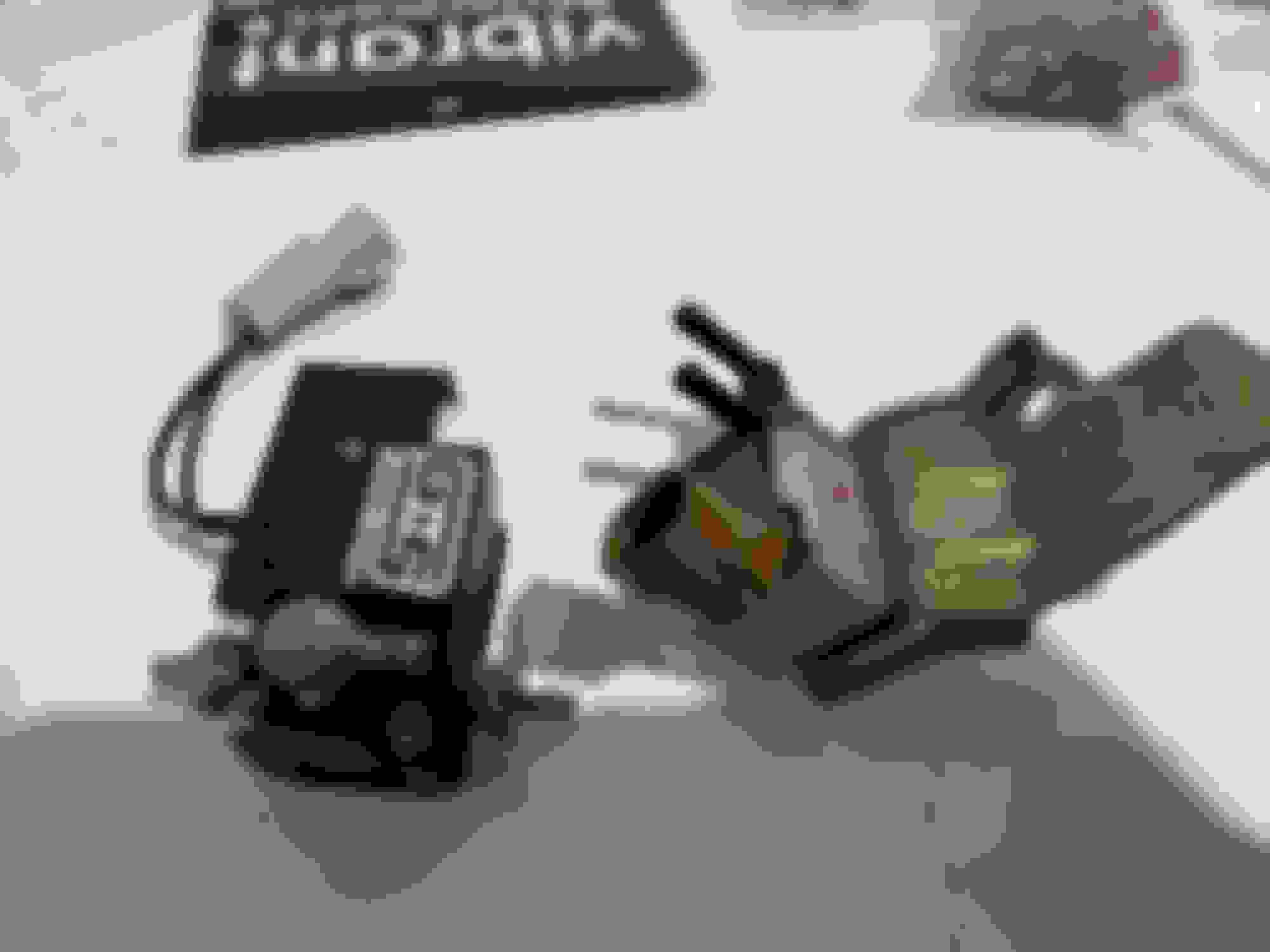
The DW300 fuel pump is visually identical to the stock fuel pump. My DW300 came with everything needed to install the fuel pump.
DW300 with everything needed to install
When I tried to start my car for the first time after installing the new fuel pump, it took about 10 seconds of cranking before the car started. The DW300 is nearly silent and cannot be heard at all if the rear seat is installed. I was only able to hear the pump when the rear seats and black hatch cover were removed and the fuel tank was exposed. When uncovered, the pump produces a quiet, very high pitched whine.
ACCESSORIES
The Japanese Yen has taken a dive recently, so I browsed around online for any Japanese parts that interested me. I came across two parts that I purchased.
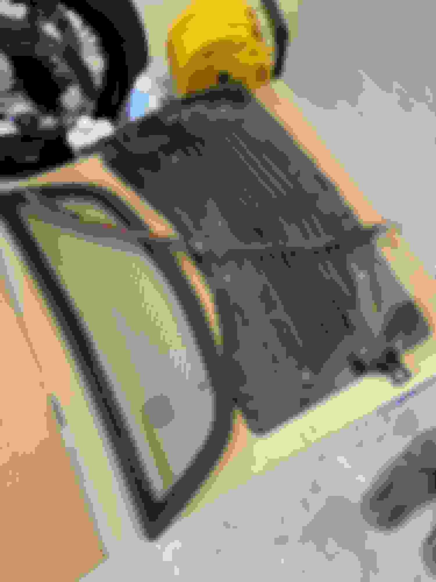
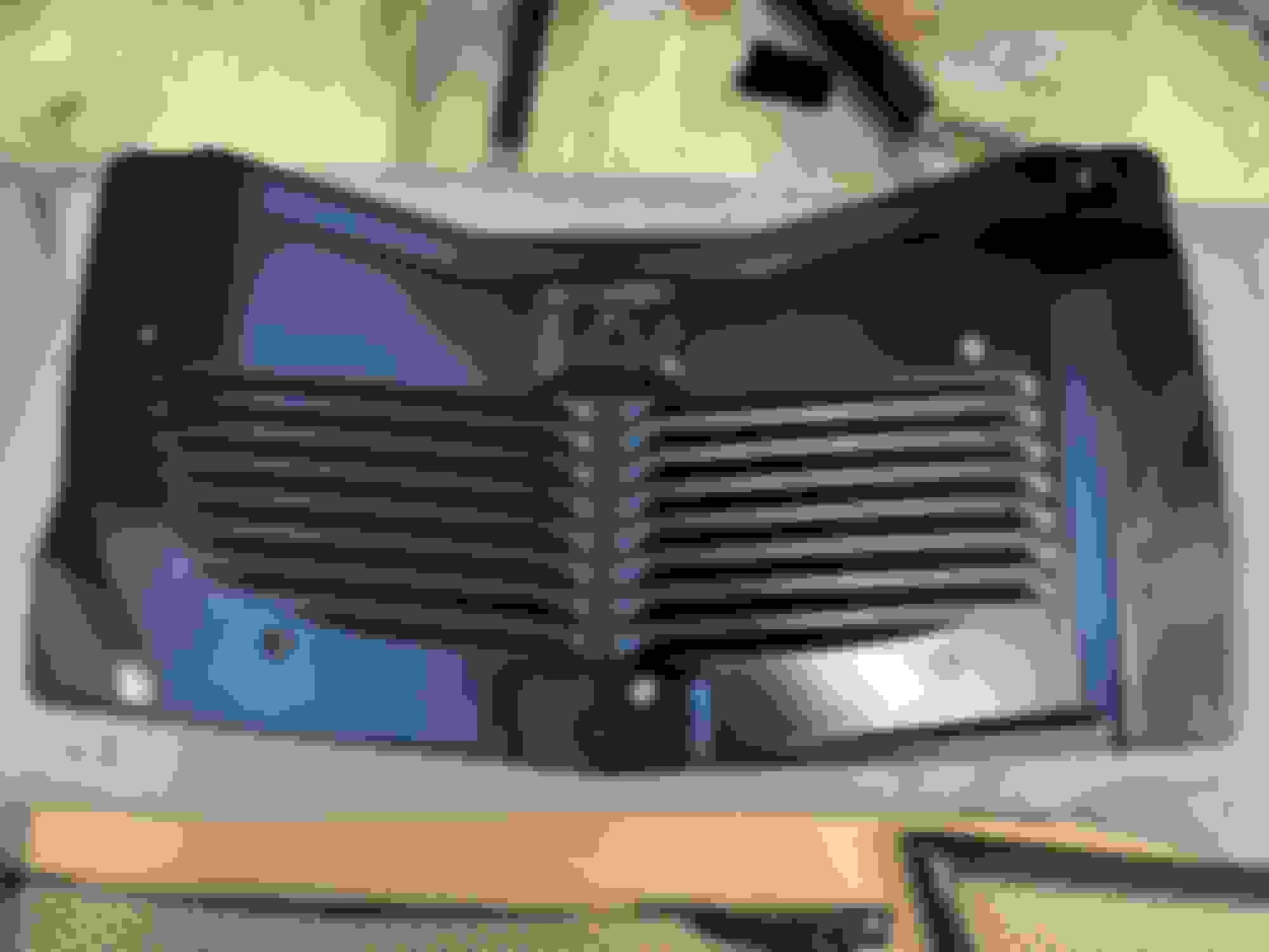
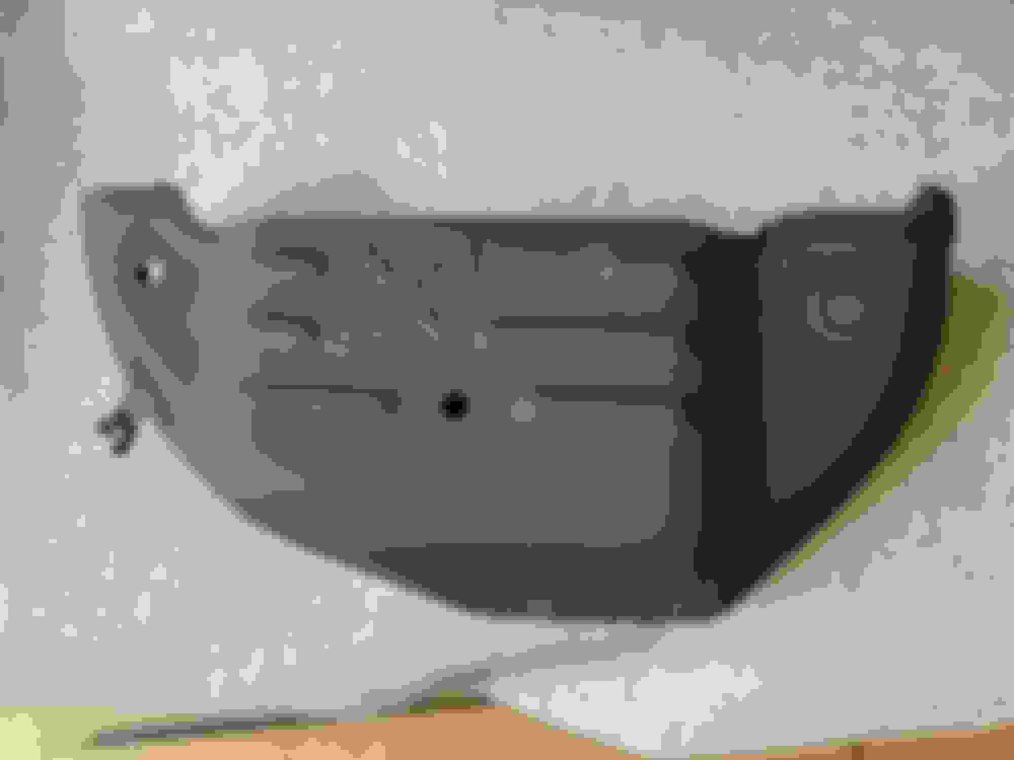
The first item I purchased was a carbon radiator shroud made by Carbing.
Carbing calls it a "cooling plate"
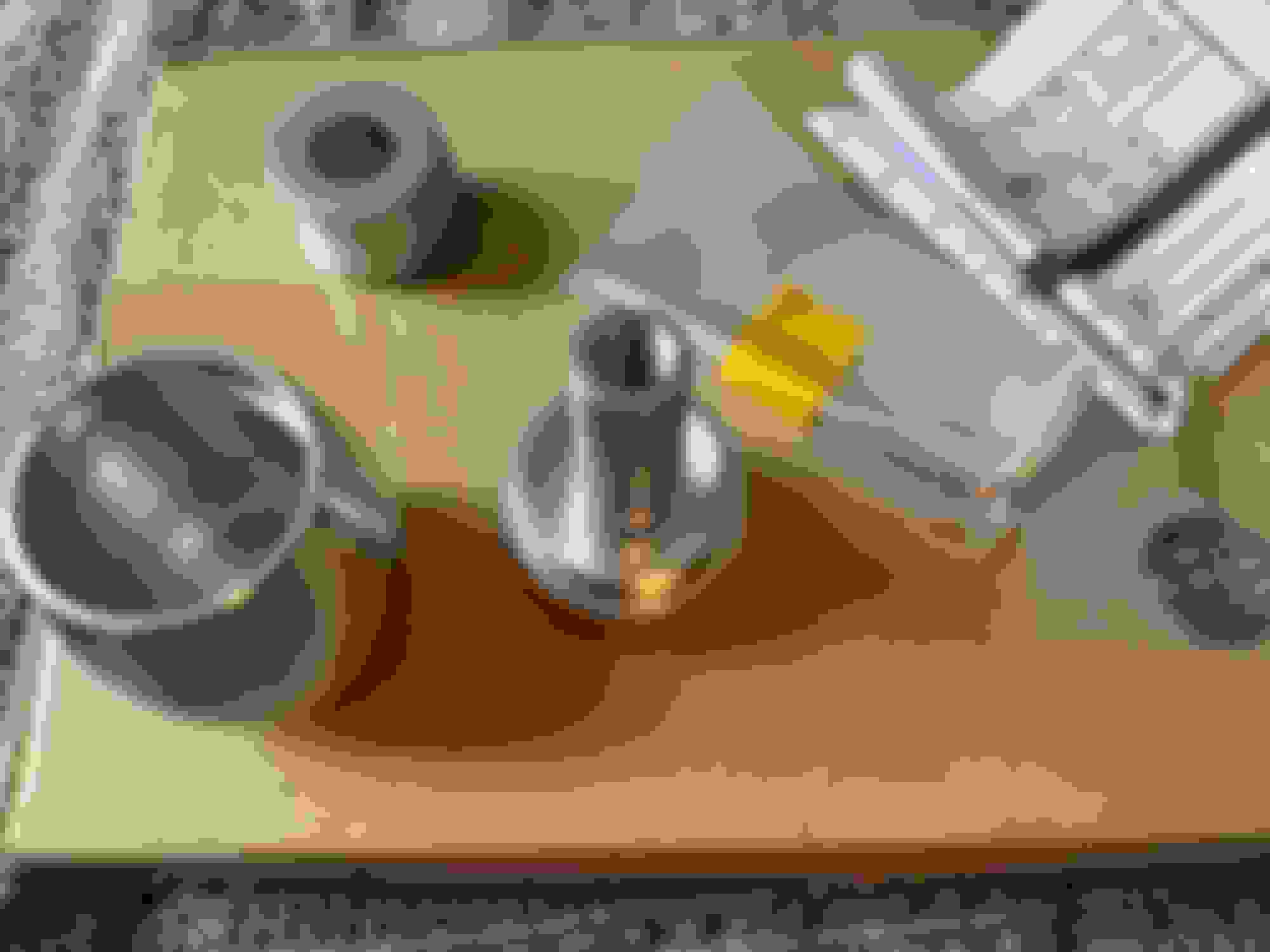
The second item I purchased was an OEM optional shift knob MZ525618. The knob is made of aluminum. The shift knob contains a stack of washers that can be added or removed to adjust the weight of the knob. The washers are held in place by a spring, and the shift knob is held together by a set screw that sits right above the base of the shift knob. The knob came with a hex key for the set screw and a 5-speed sticker, while part number MZ525617 is the same shift knob with a 6-speed sticker.
Box with Mitsubishi part number
Box contents
Disassembled shift knob. Spring not pictured
Set screw and set screw hole to prevent shift knob from unscrewing from base
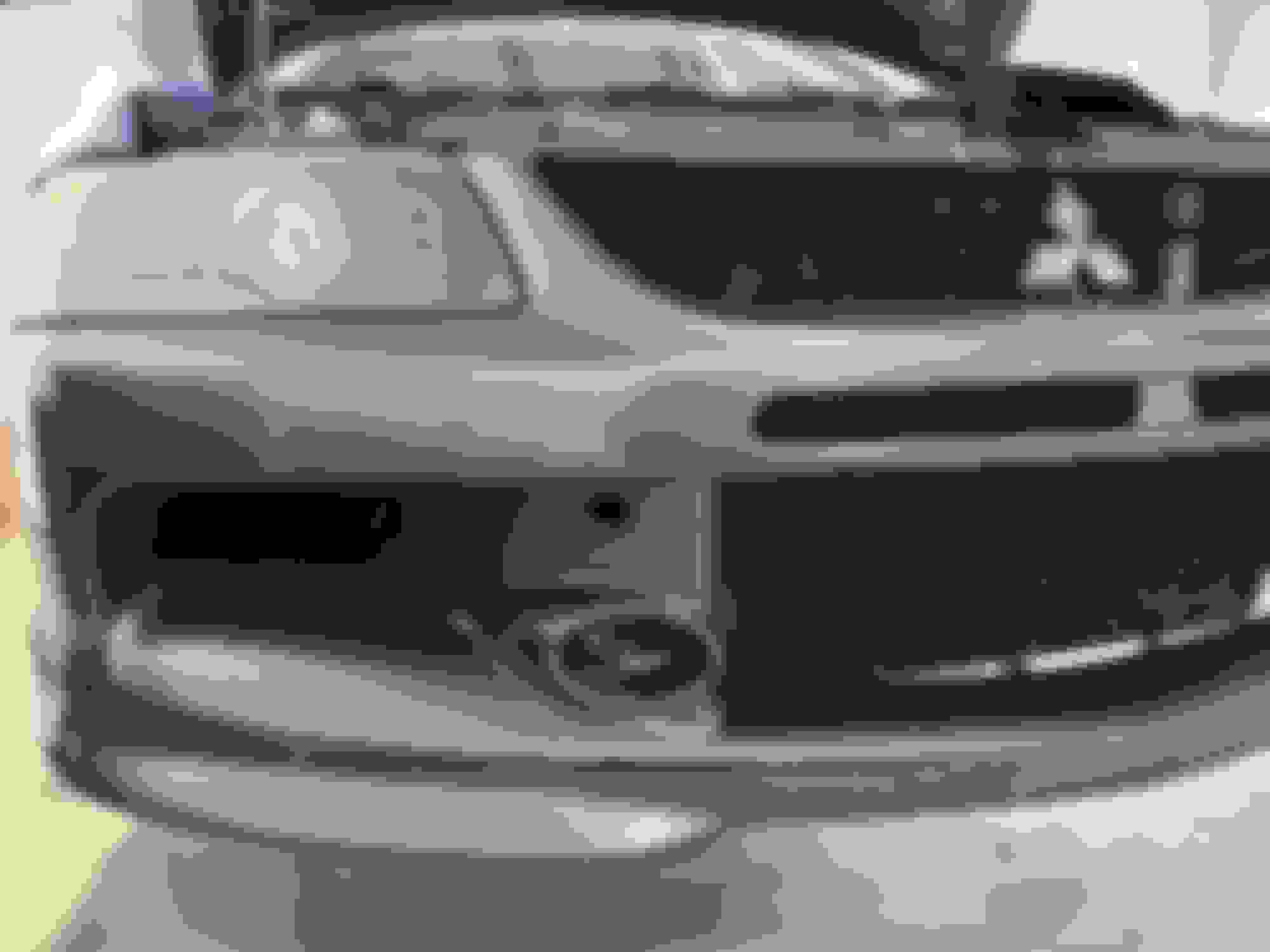
FRONT BUMPER
Removing the front bumper is necessary to access the headlights and intercooler, and made accessing the engine bay much easier. I began by taking off the undertray. Then, I removed the clips and bolts holding the bumper in place. There are clips on the top of the front bumper, clips in the wheel wells, bolts hidden behind the front license plate (accessible through the front license plate holder), and bolts hidden behind two small circular caps on the face of the bumper.
Thank the previous owner for the cracked lip
Factory undertray clips are super expensive. There are generic copies available for much cheaper
Assembled undertray
The undertray locks together using a series of interlocking and overlapping tabs. It can be difficult to properly connect the four pieces of the undertray together when installing them one at a time onto the car. If possible, I recommend finding a way to mount the undertray as one piece so that the undertray is properly connected together.
Clip on top of bumper
Clips inside wheel well
Bolts hidden behind front license plate
Tiny circular panel that pops out to reveal hidden bolt
Hidden bolt
Initially, I couldn’t get my front bumper to separate from the car. I thought something was stuck or still attached to the car. It turns out the bumper just needed a little more strength than I expected to be removed. First, pull each side of the bumper down and outwards. Once each side is separated from the car, give the bumper a strong, firm pull straight outwards and it will disconnect.
HEADLIGHTS
My headlights were super cloudy, so I looked into finding a way to make them clear again. I chose to use a 3M headlight restoration kit. The kit came with a piece of sandpaper and two wipes soaked in a solution that dries to form a shiny protective coating. Rubbing my headlights with the sandpaper produced a layer of yellow muck that I washed off the headlights before coating them with the coating wipes. I followed the included instructions and slightly overlapped my wipes on my headlights, but the coating left behind by the wipes ended up layering on top of itself. Nonetheless, my headlights looks much better than they did before, and the coating is able to be scratched off by a fingernail if I want to redo it in the future. I am interested to see how long my headlights will remain as clear as they are now.
Top layer of headlight removed after wet sanding
After coating
INTERCOOLER
I installed an ETS 3.5” wide tank intercooler. Accessing the intercooler requires removing the front crash beam, which is held in by four bolts. The intercooler I purchased comes with two couplers, four clamps, and the hardware needed to mount the intercooler. The intercooler is secured to the car by a bolt on each side and hangs from a stud that protrudes out of the car right above the intercooler.
Connecting the piping to the intercooler required taking the intercooler off of the bracket securing it to the car in order for the intercooler and piping to have enough wiggle room to fit on each side. I recommend a helping hand. One of us held the intercooler and shifted around as necessary while the other worked to fit the piping to the intercooler.
Installed
The intercooler is compatible with factory intercooler piping. The intercooler is able to fit in the factory location without any modifications. There is about a 1 cm gap between the intercooler and the crash beam. The intercooler is just barely able to clear the air guides on each side. The new intercooler is much larger than the factory unit, and also multiple times heavier.
Last edited by rustykan; Apr 20, 2024 at 01:49 PM.
I purchased an MAPerformance “O2 eliminator” downpipe. This downpipe combines the O2 housing and the downpipe into one piece. This allows the wastegate to be routed to enter the main exhaust pipe further along the downpipe, rather than the OEM style O2 housing which merges the wastegate and exhaust immediately. The idea behind merging the wastegate gases further downstream of the exhaust rather than merging them immediately is to reduce exhaust turbulence and improve flow.
Uncoated, as it came
The downpipe is 3” in diameter and made of stainless steel. The downpipe has a flex section in the middle and an additional bung welded in for a wideband O2 sensor. I sent my downpipe to Jet-Hot to have it coated.
Jet-Hot's 2000 degree coating in titanium color option. Coating is rough to the touch
Installing the downpipe required a lot of work. The removal and installation required copious amounts of rust penetrant and lots of time. One piece of advice I have is to spray seized bolts with rust penetrant multiple times and when something feels completely stuck, give the rust penetrant time (24 hours or more) to work its magic. First, the stock downpipe had to be removed, then the O2 housing. To begin, there are two braces underneath the car that are in the way and need to be taken off.
Two braces that prevent downpipe from dropping
The factory downpipe is secured by two exhaust hangers near the cat, as well as two bolts on each end of the downpipe. The two bolts connecting the downpipe to the O2 housing are wrapped in springs but are not under any tension so don’t be afraid to break them. The two bolts connecting the downpipe to the catalytic converter were thoroughly rusted through and required a torch to remove. I used Windex and a hanger removal tool on the hangers to slide them off.
Stock downpipe with heat shields
I have read posts on this forum of people removing the O2 housing without removing anything else besides the downpipe, but I have no idea how they did it. The O2 housing is secured by nuts that aren’t accessible with a breaker bar. I realized the easiest way to remove the O2 housing was to split the turbo in half and remove the O2 housing and turbo turbine housing as one connected piece.
To gain access to the turbo, the exhaust manifold has to be removed. There is minimal space in this area of the engine bay, and the radiator gets in the way of removing the exhaust manifold, so I decided to remove the radiator. To remove the radiator, first drain the radiator by removing the radiator cap then unscrewing the plastic tap on the bottom passenger side of the radiator. Then, remove the line connecting the radiator and the coolant reservoir tank, and both upper and lower radiator hoses. Next, the radiator fan controller has to be unplugged before the radiator can be removed. To make room, I removed a portion of upper intercooler piping and couplers near the radiator. The fan controller can be disconnected from below, and the fan left attached to the radiator, but I instead decided to remove them separately before removing the radiator.
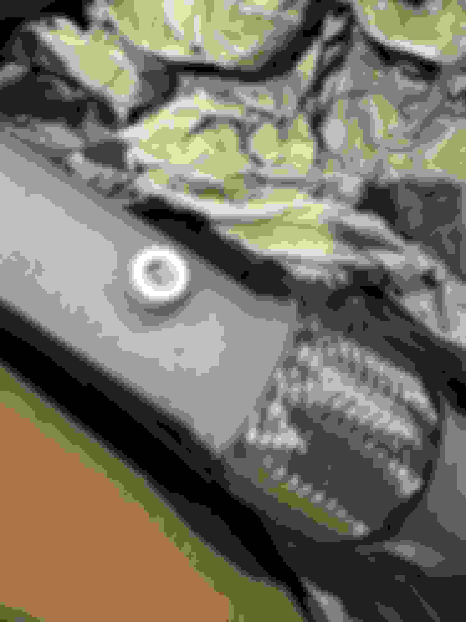
Drain tap
Overflow tank connection
Radiator Fan
Fan controller disconnected
Radiator removed from car
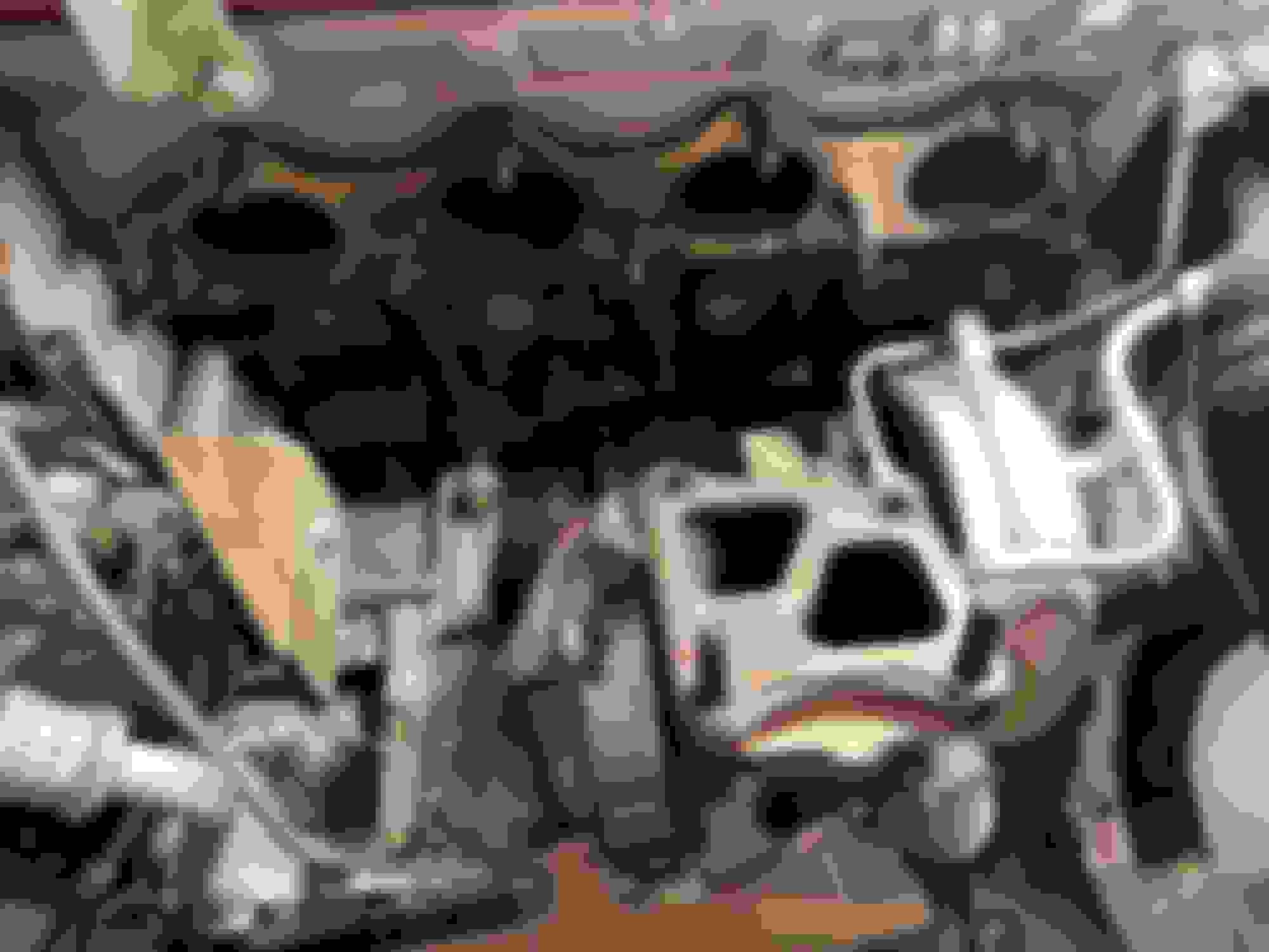
Now that more space has been freed up in the engine bay, I started working on the exhaust manifold. I began by removing the upper and lower exhaust heat shields. The top heat shield came off without an issue, but some of the bolts securing the bottom heat shield were rusted through and wouldn’t come out. Fortunately, the bottom heat shield is connected to the O2 housing, which is being removed as well, so the heat shield being stuck ultimately didn’t matter. The MAP downpipe does not have provisions to mount the lower exhaust heat shield.
There are nine studs and nuts that secure the exhaust manifold to the engine block. The turbo is connected to the exhaust manifold by two bolts and two studs. I soaked all the hardware in rust penetrant multiple times and let everything soak for about a day, which made everything easy to break. All hardware was easy to access. Accessing the leftmost nut on the exhaust manifold required removal of a small metal heat shield that was in the way. The little heat shield is held in place by two bolts.
Heat shield I had to temporarily remove to access leftmost nut
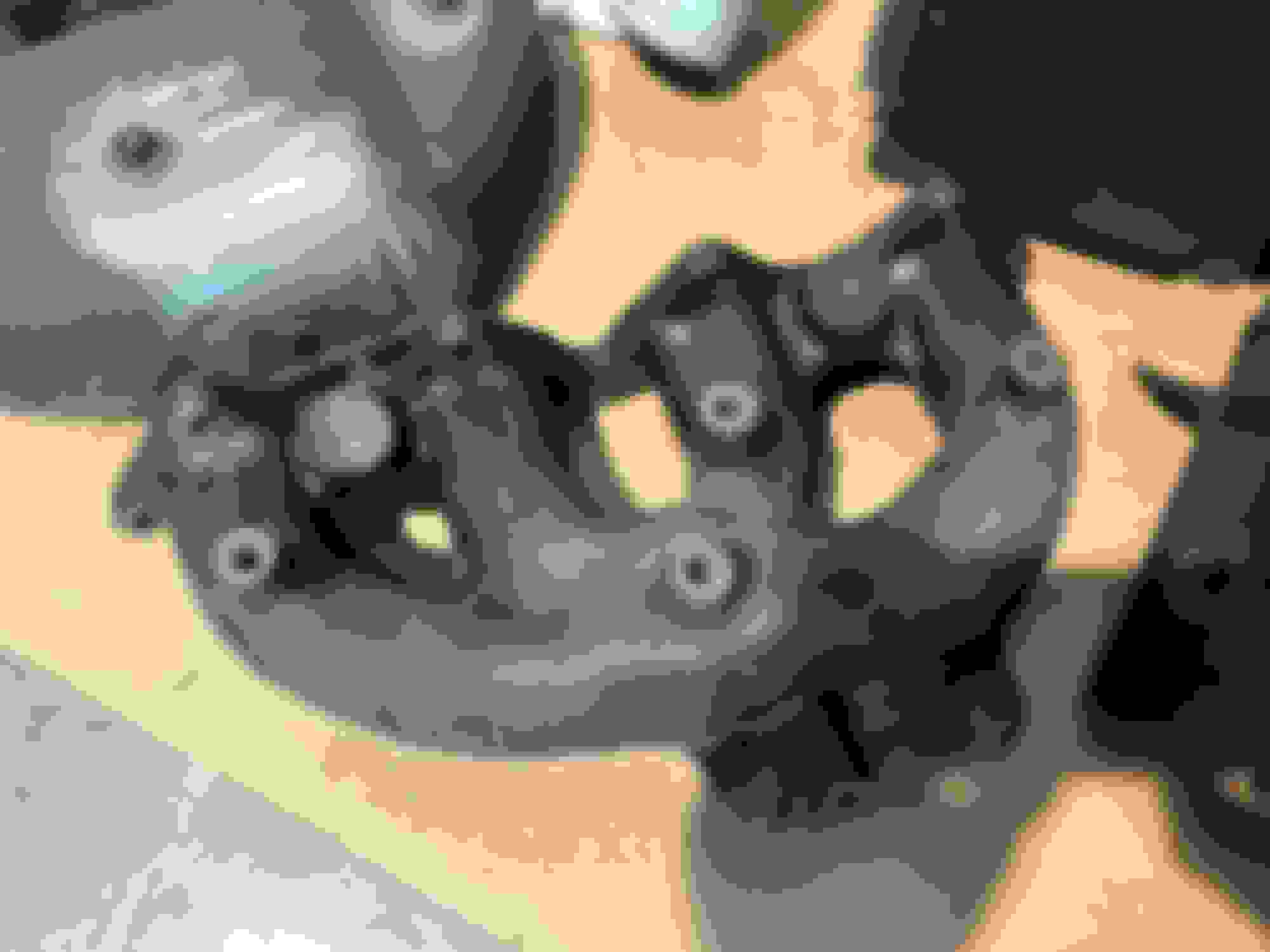
Removing the exhaust manifold requires slipping the manifold off the studs protruding from the block and from the turbo. Luckily, when the turbo is only secured by its oil hardlines, it is able to move downwards just enough for the manifold to clear the turbo studs. The turbo is connected to the O2 housing, which is secured to the engine block by a small bracket that is accessible from underneath the car. This bracket needs to be disconnected from the engine block first before the turbo will move around. There is one bolt connecting the engine block to the O2 housing bracket.
O2 housing bracket with bolt visible
Once the bolt securing the O2 housing bracket to the engine block is removed, the turbo and O2 housing will move around if pushed hard enough. Push down on the turbo and slip the exhaust manifold flange off the turbo studs. Then, pull the manifold off the studs coming from the engine. There is a multilayer gasket between the exhaust manifold and the engine, and a very thick gasket between the manifold and the turbo.
Gaskets on engine and turbo
After removing the exhaust manifold, I tried again to remove the O2 housing. There are three bolts and two nuts holding the O2 housing to the turbine housing. Since I couldn’t remove the lower heat shield, I used shears to cut the heat shield to help gain access to the bolts and nuts around the O2 housing. I was able to access and break the three bolts around the outside of O2 housing, but the two remaining nuts were tucked between the O2 housing and the turbine housing. There wasn’t enough space to fit the tools needed to break the two nuts, so I continued on with my plan to split the turbo and remove the O2 housing and turbine housing together.
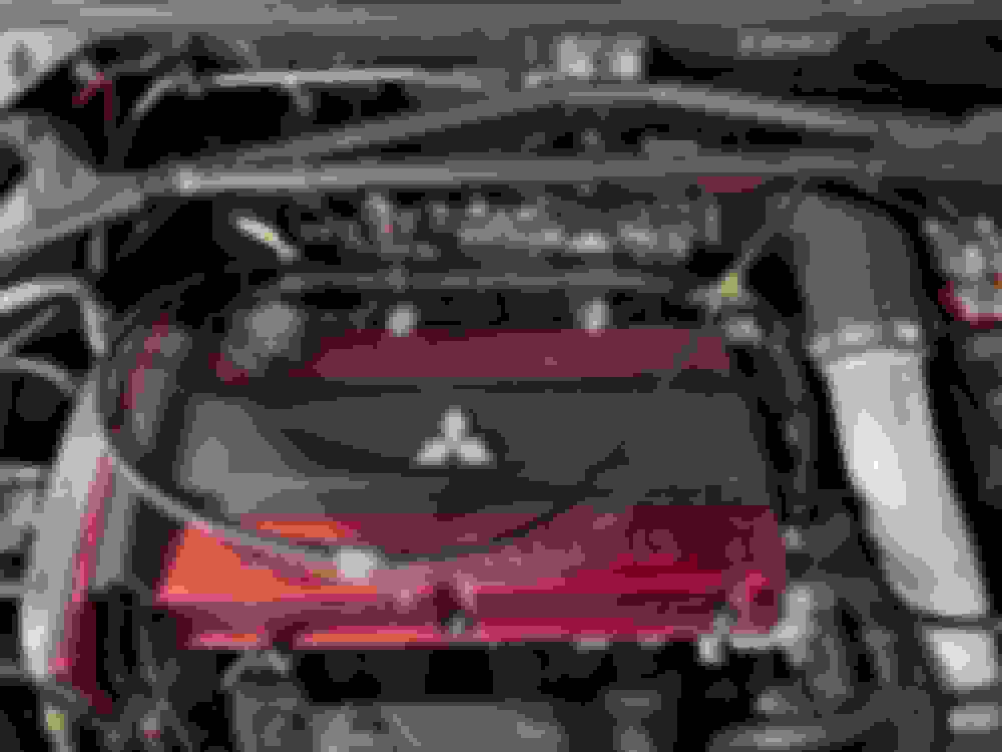
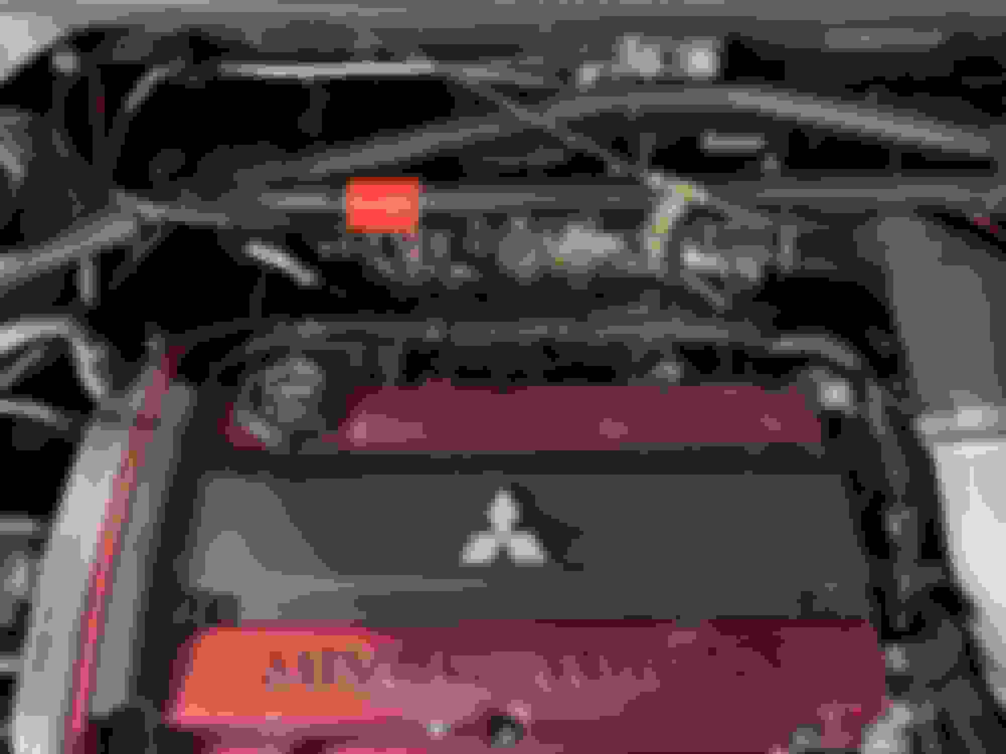
There is an O2 sensor installed in the O2 housing. I decided to leave it in and instead disconnect the sensor so I could attempt to remove O2 sensor from the O2 housing outside of the car. The O2 sensor connection is located underneath the plastic coil pack cover on the top of the engine. The connector is secured to the valve cover by a metal bracket that is bolted down with two bolts. I chose to unbolt the connector and deal with removing the bracket later.
Underneath coil cover
O2 sensor connector attached to metal bracket
After disconnecting the O2 sensor, the next step was to disconnect the wastegate actuator from the turbine housing. The actuator arm is secured to the turbine housing by a cotter pin. My cotter pin was thoroughly rusted through and snapped when I tried to remove it. I had to use a very tiny chisel and hammer to remove it.
Finally, the hot and cold sides of the turbo are held together by a v-band clamp. After removing the bolt securing the clamp together I tried to remove the clamp, but it was seized shut. I liberally sprayed the clamp with rust penetrant and waited 24 hours. When I returned the next day, the clamp came apart with no resistance.
V-band clamp visible
V-band clamp removed
At this point the turbo is ready to be cracked in half. My turbo would not come apart easily. Due to rust, I had to use a rubber mallet to free the hot side from the cold side. There is a small pin that protrudes from the hot side mating surface and sits in a hole in the cold side mating surface, ensuring that the two halves always fit together the correct way. When the two halves of the turbo are separated the turbine wheel is exposed. Do not let the turbine housing strike and damage the turbine wheel. The cold side has to be pulled outwards to make room for the turbine housing to clear the turbine wheel. The O2 housing and turbine housing are very heavy.
Turbine wheel close-up
O2 housing and turbine outlet with O2 sensor
With the O2 housing and hot side out of the car, I was able to separate the two pieces by securing them with a vice and breaking the two nuts tucked away on the inside of the O2 housing. The factory O2 sensor was completely seized, so I made the decision to buy a Denso replacement O2 sensor (part number 234-4741) and ditch the old one. I did remove the metal bracket attached to the sensor connector and transfer it to the new O2 sensor.
Nuts tucked away on the inside of the O2 housing
Bracket for O2 sensor connector
Accessing the nuts on the inside of the O2 housing section of the new downpipe would be impossible with the turbo hot side installed in the car, so I connected the turbine housing to the downpipe and reinstalled them together as one unit. The MAP downpipe did not come with new installation hardware, so I cleaned up and reused the factory nuts and bolts to connect the downpipe to the turbine housing. I also plugged the wideband bung in the new downpipe. I purchased an AEM wideband controller but am not going to install it for the time being. I applied nickel anti-seize to every nut and bolt installed in the downpipe.
Turbine housing mounted to downpipe
Wideband bung closed
Reinstalling the downpipe without damaging or scraping any surrounding components in the engine bay absolutely requires two people. To install the downpipe, the entire downpipe had to be lowered from above the engine bay down through the area where the turbine and O2 housing sit. Then, one person worked on reconnecting the turbo halves and properly seating the pin while the other crawled under the car and helped support the weight of the downpipe. After the turbo halves were connected, I connected the downpipe to the two exhaust hangers under the car and installed the v-band clamp, repositioning the clamp bolt to be easily accessible from underneath the car.
Downpipe mounted to hangers
Downpipe connected to turbo
V-band clamp bolt repositioned to be accessible from under car
Instead of coming with the bolts necessary to connect the downpipe to the factory catalytic converter (M12x1.25) the downpipe came with M12x1.5 bolts and M12 nuts. I thought these nuts and bolts were sent to me by mistake, but when I reached out to MAP customer support I was told that the bolts supplied are for an aftermarket test pipe (I don’t understand the reasoning behind this). I purchased zinc coated bolts and washers of the correct size and used those to install the downpipe to the catalytic converter.
The new downpipe is too wide to clear the frontmost bracer underneath the car, so included with the downpipe are three long bolts and spacers that are used to make the brace clear the downpipe. The factory bolts used to mount the brace had split washers, so I went out and bought some of those too.
Spacers installed, brace barely clears downpipe
I made sure to reattach the wastegate arm to the flapper and install a new cotter pin.
New cotter pin
RESTORATION
A lot of painted parts in and around the engine bay were in rough shape, so while everything was off the car I decided to sand and paint a few pieces. I painted a piece of wire mesh and a metal bracket from the front bumper, I painted the hood vent and restored its rubber surround, I painted the metal vented cover that sits beneath the hood vent, and finally I sanded and painted the exhaust manifold heat shield. I forgot to use high temperature paint on the hood vent and vent cover, so the paint on those pieces may not last very long. If the paint flakes off of those parts I will go back and repaint them with high temperature paint.
Rusty, old pieces
Bumper mesh
Bumper bracket
Hood vent with rubber surround
Hood vent cover
Exhaust manifold heat shield top
Exhaust manifold heat shield bottom
BOOST CONTROLLER
I replaced my stock boost controller with a GrimmSpeed 3-port Boost Control Solenoid. It is my understanding that the stock boost controller connects the boost source (turbo) with the wastegate, causing the wastegate to always open a certain amount under boost. A 3-port solenoid separates the boost source and wastegate, and the ECU controls when the wastegate sees pressure. This way, the wastegate does not open prematurely, allowing the turbo to produce more boost.
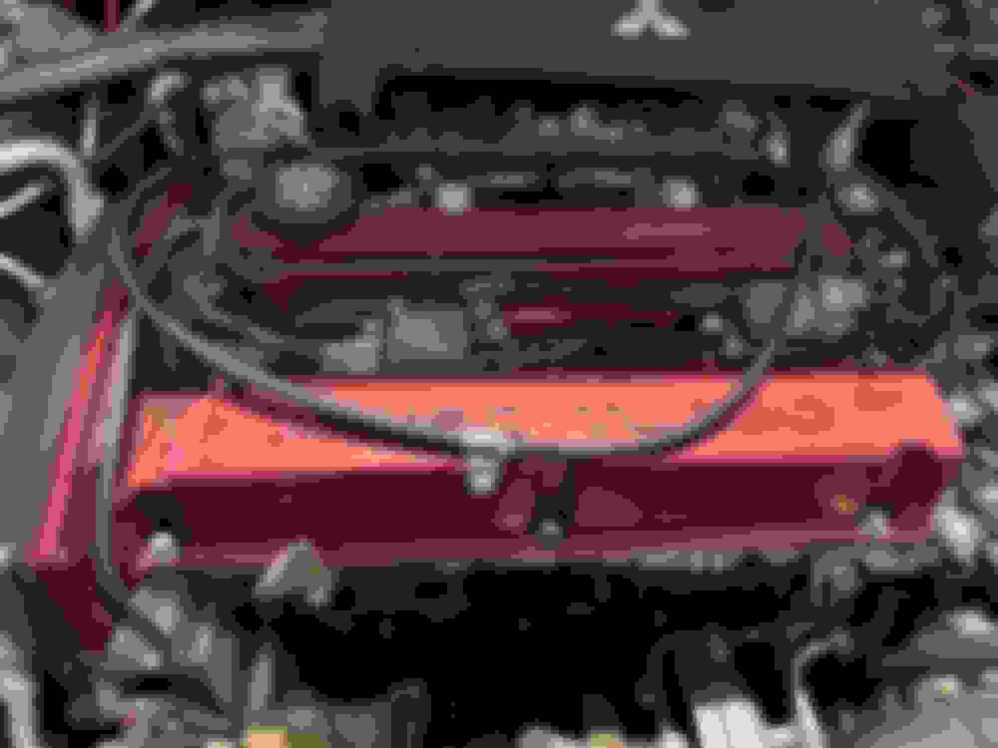
The stock boost controller is located underneath the intake, bolted to the frame of the car. My car came with an aftermarket intake, so I won’t go over how to remove the intake to access the boost controller. The stock boost controller has two vacuum lines and an electrical plug. One vacuum line runs to a nipple hidden underneath the turbo inlet. The second vacuum line connects to both the turbo compressor outlet (boost source) and wastegate. The GrimmSpeed solenoid mounts in the same location as the stock boost controller and comes with the correct electrical connector, making it plug-and-play. The GrimmSpeed solenoid connects to the same places as the stock solenoid but separates the turbo compressor outlet and wastegate vacuum lines. I ended up breaking the vacuum nipple underneath the turbo inlet so I replaced it with a generic nipple.
Box
Box contents
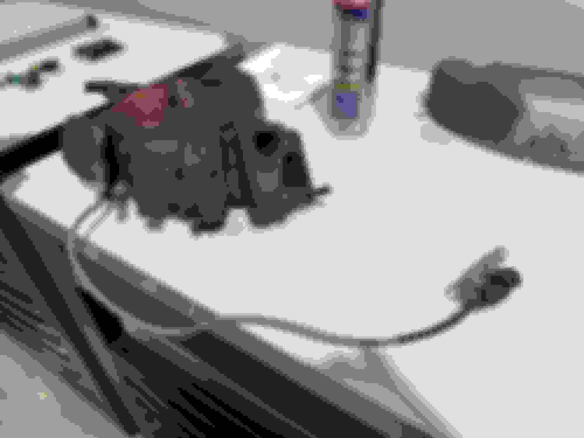
Factory boost controller
Comparison, 3-port vs 2-port
GrimmSpeed EBCS mounted in factory location
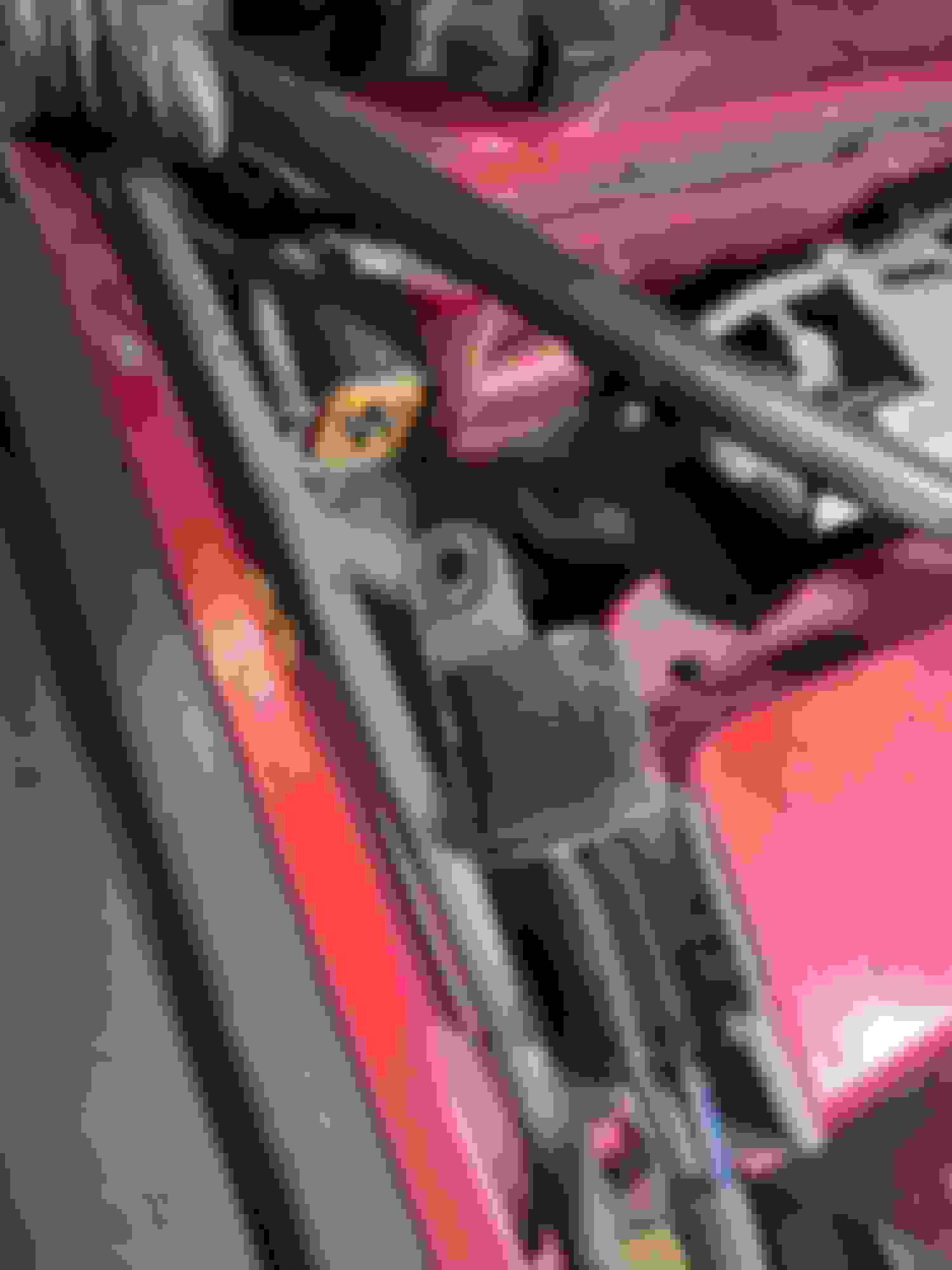
Stock vacuum line connects to both turbo and wastegate
Line disconnected from both nipples
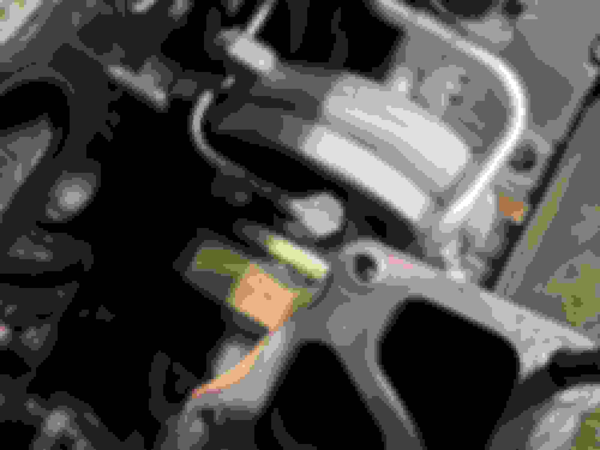
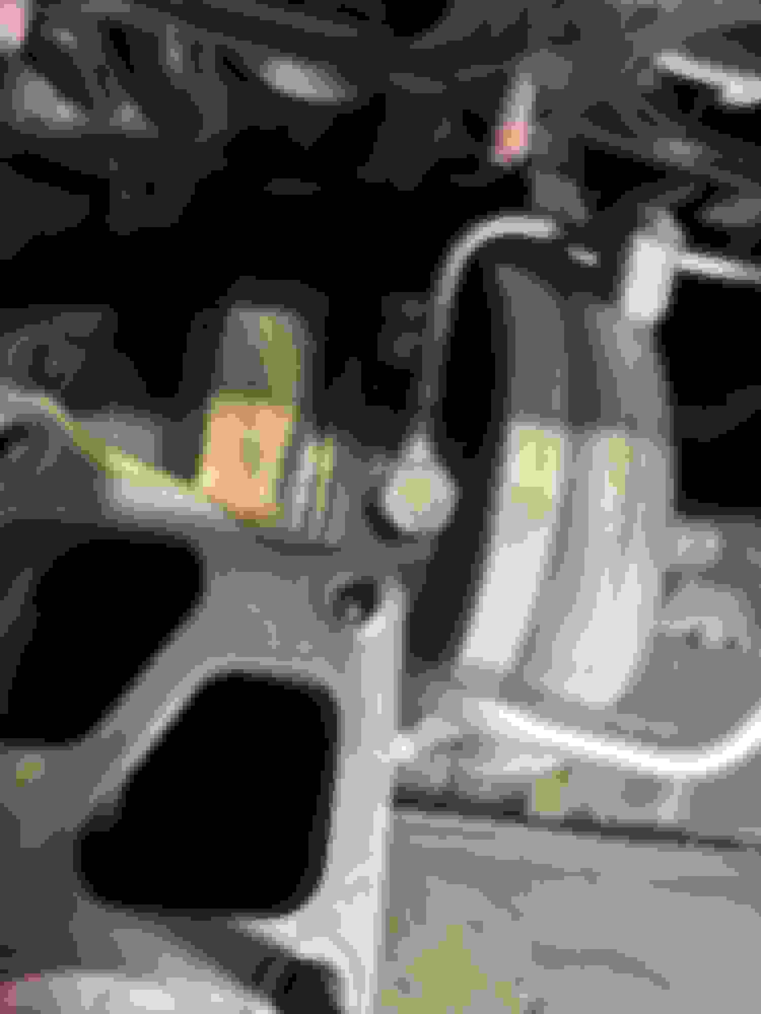
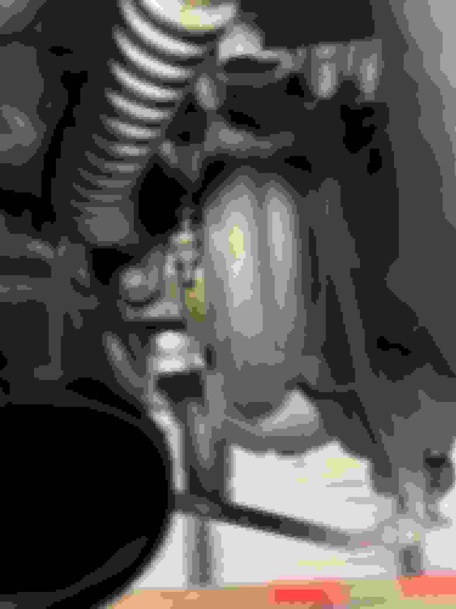
Nipple location hidden under turbo compressor inlet pipe
Turbo compressor inlet nipple replaced after breaking
Installing my injectors was the most frustrating modification I have made so far. There is a bunch of wiring, tubing, and hardlines that get in the way of the injectors, which makes accessing them a pain.
I am only interested in running 93 octane gas, so I went with Injector Dynamics 1050x injectors. The injectors came with electrical adapters that make them plug-and-play. I also purchased an FIC resistor pack delete plug. The factory injectors are low impedance, which require resistors to function properly. These resistors are stored in a little metal box bolted to passenger’s side firewall. My new ID injectors are high impedance, which do not require resistors. In order to switch from low impedance to high impedance injectors, the car’s resistor pack has to be disconnected and the electrical connection to the pack terminated. The resistor pack delete plug connects to the wiring leading to the resistor pack to prevent an open circuit.
Box
Box contents
FIC resistor pack delete plug
I began by disconnecting the fuel pump (accessible under the rear seat, pull the gray electrical plug) and starting the car. This was to minimize the amount of fuel sitting inside the fuel rail. The car ran for less than a second before dying.
Disconnect gray plug
I started off by trying to move some of the clutter away from the injectors for easier access to them. I unbolted the throttle cable and taped it to the strut tower bar. I also unbolted the injector wiring harness from the valve cover.
Disconnect throttle cable
Tape throttle cable out of the way and unbolt injector wire harness
The injector electrical plugs are secured to the injectors by springy wire clips that fit in a groove that runs around the edge of the electrical plug. I used a small flathead screwdriver to separate the clips from the injectors, then grabbed the clips using needle nose pliers. After removing the clips I disconnected the injectors. I tried to tape the connector wiring out of my way but the tape wouldn’t stick.
Injector plug clip still installed
Injector plug clip unseated
Injector plug clip
Disconnected injectors
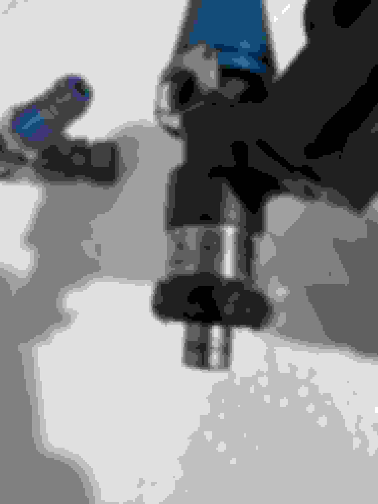
The fuel injectors are held in place by the fuel rail. The fuel rail is held in place by a hardline that connects on the driver’s side of the fuel rail and two bolts that connect the fuel rail and fuel return line to the intake manifold. The fuel hardline is hidden beneath the fuel return line. The hardline is connected to the fuel rail using two bolts. Remove the two bolts holding the hardline in place, and the hardline can be disconnected from the fuel rail.
Fuel return line with fuel hardline hidden underneath
Fuel hardline disconnected from fuel rail
After removing the hardline remove the two bolts holding the fuel rail in place. One is clearly visible, the other is hidden on the other side of a bracket. After removing the bolts connecting the fuel rail to the intake manifold, remove the black plastic spacers that separate the fuel rail brackets and the intake manifold. Now the fuel rail can be pulled upwards away from the intake manifold, allowing the old injectors to be removed.
Left bolt securing fuel rail
Right bolt securing fuel rail hidden behind bracket
Plastic spacer seated
Plastic spacer removed
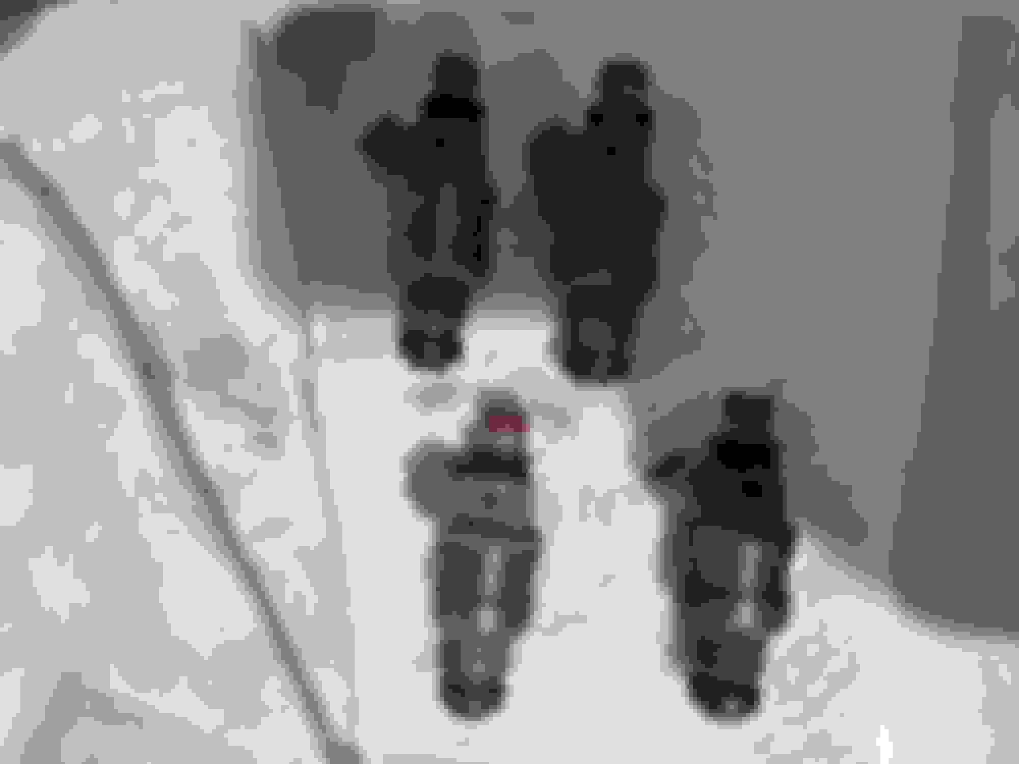
Stock injectors removed
Stock low impedance injectors
When installing the new injectors, I made sure to apply ample silicone grease to both the small O-ring on the top of the injector that sits in the fuel rail, and the large plastic spacer on the bottom of the injector that fits in the intake manifold. After connecting the electrical adapters onto each injector, I pushed them into the intake manifold until I felt them seat. The large plastic piece that I lubed on the bottom of the injectors would pop into place and hold the injector steady while I reinstalled the fuel rail.
Lubricate top O-ring
Lubricate bottom spacer
New injectors installed
Finally, I installed the FIC resistor pack delete plug. To do so, I first unbolted the relay in front of the resistor pack from the firewall. Then, I unplugged the resistor box and terminated the electrical connection by connecting the delete plug.
Relay blocking view of resistor box
Resistor box disconnected and electrical connection closed by FIC plug
Those are all the modifications I have made to my car so far. I have a tune scheduled for next Monday. My goal is to max out the stock turbo.
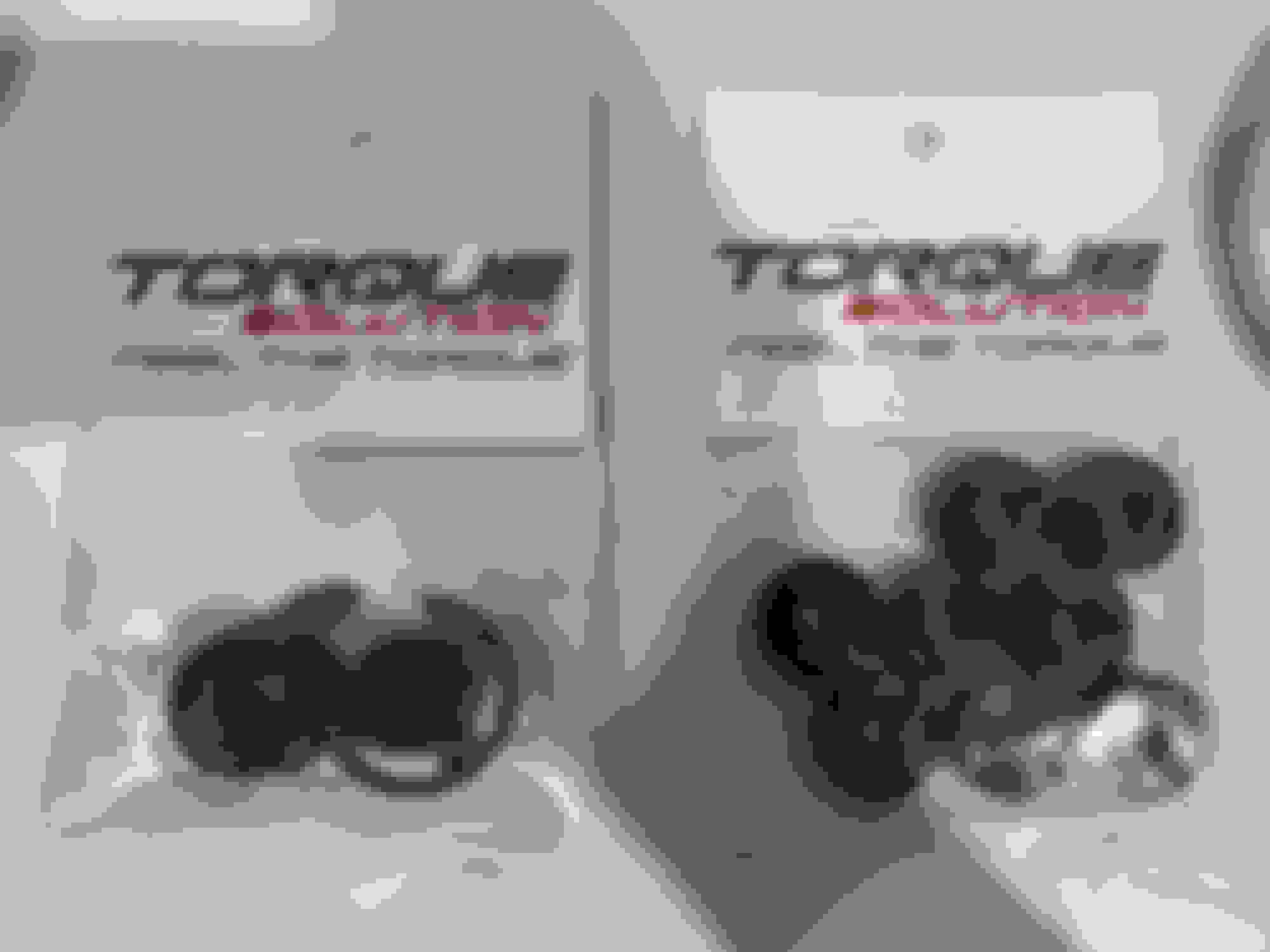
On an unrelated note, my shifter does not move smoothly from left to right. I purchased Torque Solutions under hood and shifter base bushings in an attempt to remedy the shifter problem. I will install these bushings in the future.
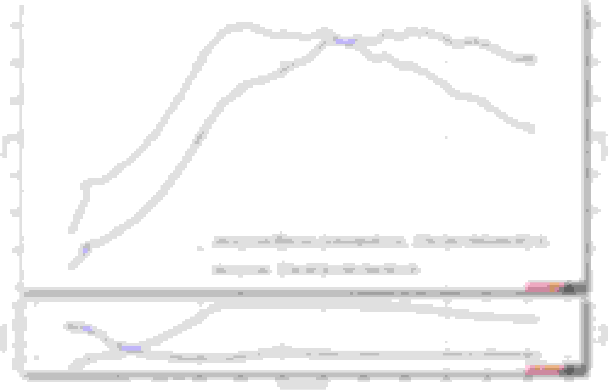
If everything goes smoothly (fingers crossed) I will update this thread in one week with a dyno chart.
The car made 340HP and 350TQ. My favorite aspect of the car being tuned is that it drives exactly the same way it did before. No sacrifices had to be made to make the car faster (besides a louder exhaust note, if you consider that a sacrifice).
I believe the stock turbo and clutch are both at their limits, so if I want more power both will need to be upgraded.
I have run out of money so the car will remain in this state for the time being. My next round of mods will be an MHI-18k, GSC S2s, and an Exedy organic single disc. I'm hoping those mods will help the car reach 400+ HP.
The stock 9 turbo can do over 400hp with E85. Some mild cams like an S1 pair well with it. S2 and an 18k also pair well but are overkill if your goal is 400hp.
Exedy clutches are good, but if you're going with their stage 1 clutch you will want the heavy duty pressure plate. I had their stage one with a standard pressure plate and it began slipping at 400. Now I have an ACT clutch, zero issues and has held power great.
Over the holidays I replaced my front speakers and tweeters.
I chose Infinity's 6.5 in. Reference 6530cx component speaker set. The set came with two speakers, two tweeters, two crossovers, and brackets that house the speakers and tweeters. I used Deutsch connectors to connect everything together.
Alongside the speaker set, I also purchased:
speaker wire – Instead of tampering with the inadequate factory wiring, I decided to run new speaker wire.
back straps – The new tweeters did not have a way to mount to the factory tweeter locations, so I created mounts for them using back straps.
screws to mount the door speakers to their plastic brackets – The speaker set did not come with screws to mount the speakers to their brackets, so I purchased some from my local Ace Hardware. I did not take a picture of the screws I purchased. They were shallow and had a wide head.
Component speaker set with Amazon wiring and back straps
WIRING PREPARATION
My wiring setup does not utilize any factory wiring to power the front speakers or tweeters. Speaker wire for the left speaker and tweeter begins at the head unit and leads to a crossover, which is mounted somewhere behind the dashboard. From the crossover, wiring runs into the door and powers the door speaker. Additional wiring runs from the crossover into the A-pillar to power the tweeter. The right crossover, speaker, and tweeter are set up the same way.
To begin, I cut the positive and negative wires in the head unit harness that connect to the front left and front right speakers (the tweeters do not have their own dedicated wiring from the head unit. The factory crossover is hidden/built-in somewhere). I soldered the left wiring and right wiring to small sections of my new speaker wire and finished both off with Deutsch connectors. At this point the head unit was ready to connect to the left and right crossovers.
Head unit harness, speakers, and tweeters prepped with Deutsch connectors.
DOOR SPEAKERS
I'm skipping over the door card removal process because it was straightforward.
I adapted generic OEM style speaker connectors using Deutsch connectors in order to to connect the speaker wiring to the speakers. The most difficult part of this installation was running speaker wire into each door. I used fishing tape to feed speaker wire through the factory grommets connecting the doors to the body of the car. This took time and patience, as the grommets were filled with other wiring and positioned at weird angles. To help me feed the fishing tape through the grommets, I tried to straighten out the grommets as much as possible by unbolting the door stops, allowing the doors to open more than usual. The speaker brackets also required trimming of their "ears" in order to fit, which I also had to do previously in order to allow the rear speakers to mount properly to the rear decklid.
Fishing tape used to feed speaker wire into door.
New speaker wire fished through factory grommet
The factory door wiring was sealed to the grommets using electrical tape. I had to remove this electrical tape when fishing the speaker wire from the body of the car and into the doors. After the new wire was ran, I resealed the grommet using new electrical tape.
New speaker screwed into bracket and mounted in door.
I used painter's tape to secure the old factory speaker connector to the wiring for the door controls. I chose painters tape because it is gentle and doesn't leave adhesive behind.
TWEETERS
To remove A-pillar trim just pull it off. No screws.
Creating mounting brackets for the tweeters required some creative work involving wire cutters and files. The factory tweeters are angled towards the cabin. The speaker set included some plastic housings which I used to recreate the angle of the factory tweeters. These plastic housings mounted to back straps I cut and filed down to recreate the shape of the factory tweeter housings.
New tweeter in plastic housing and homemade mounting bracket. I had to cut the long black screw protruding beneath
New tweeter mounted in factory location.
CROSSOVERS
Accessible space is very limited beneath the dash. I used adhesive backed velcro straps to mount the crossovers.
Crossover mounted under dashboard.
The factory speakers would produce increasingly distorted audio as I turned the volume up. This made even listening to the news difficult. My audio quality is now noticeably better, though these speakers do need a dedicated amp to reach their full potential. I am satisfied.
FUTURE PLANS
Originally I planned on reaching FBO (bolt-on turbo, cams, etc) but have decided to skip this "phase" and move straight into building the car. Building the engine has always been my ultimate goal, and I'd rather invest my money in parts I know I will keep rather than buying parts that are temporary. I've already started to accumulate some of my endgame parts. The shopping list is very long and my pockets are pretty empty, but it will happen.
Earlier this winter I decided to take advantage of the weak Japanese yen and purchased a set of wheels and a new strut brace from RHDJapan. Even with international shipping costs it was cheaper to purchase these items from overseas rather than domestically.
WHEELS
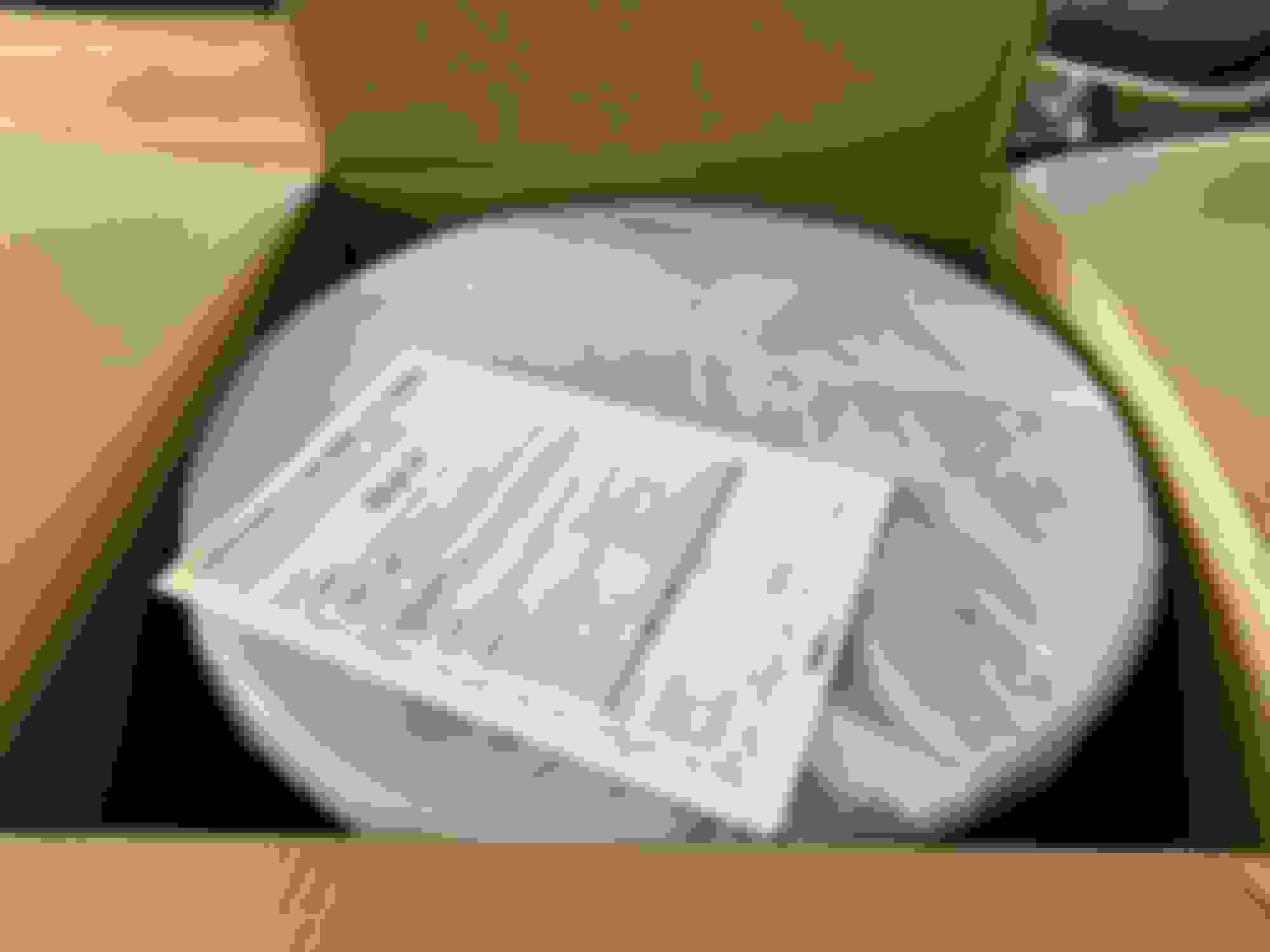
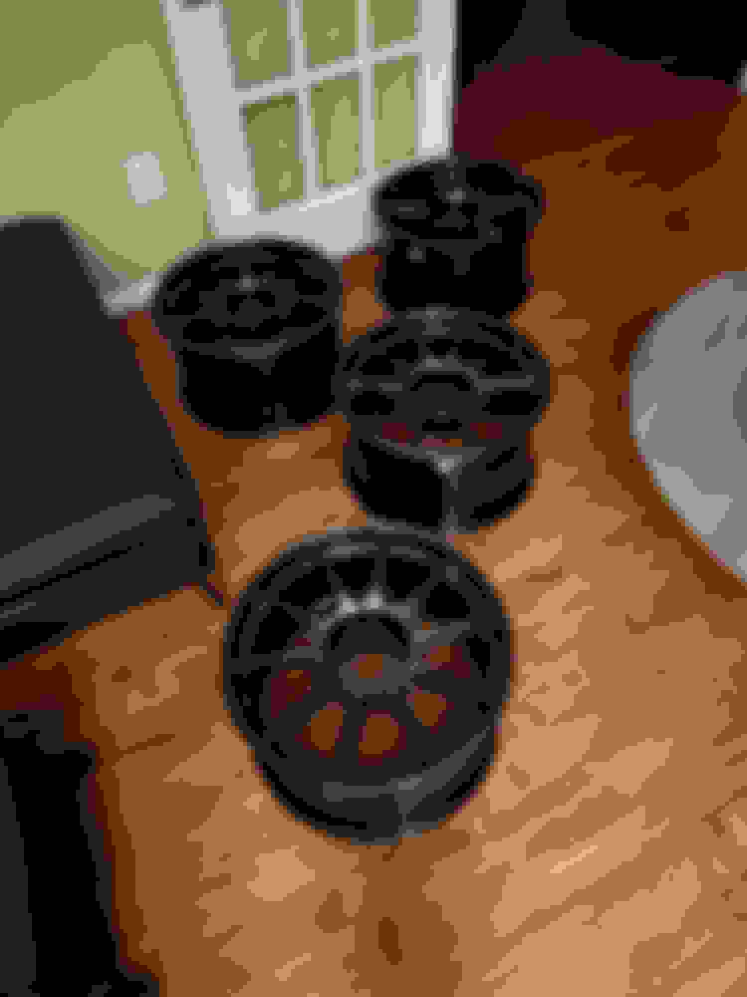
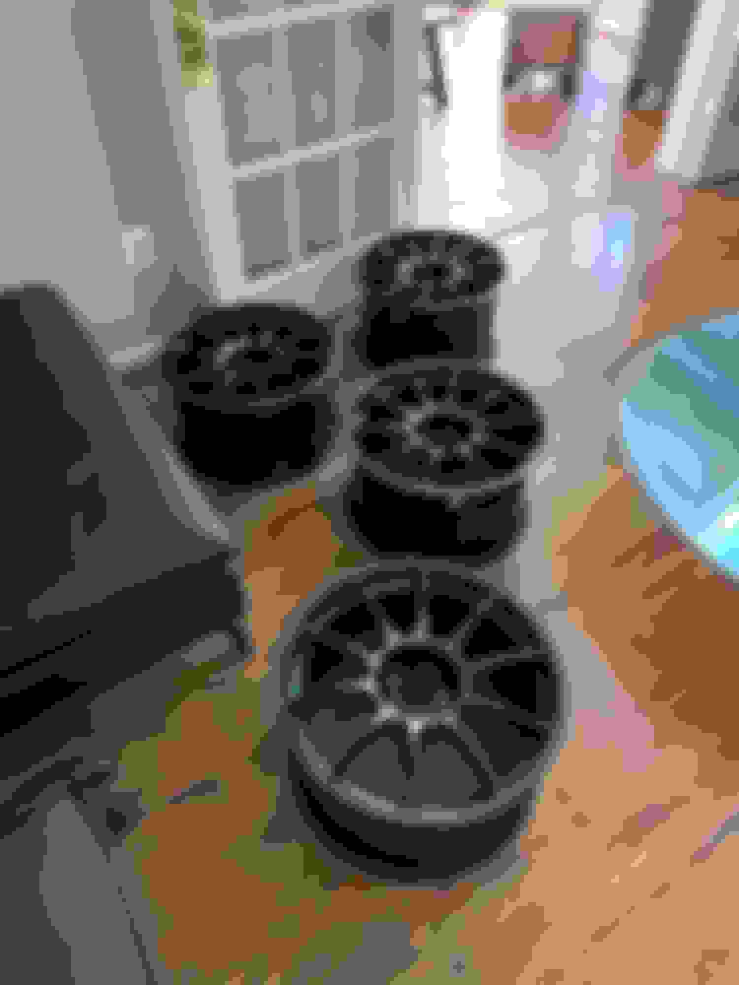
I ordered a set of WedsSport TC105X in 18x10 + 35.
They were delivered as two stacks of two wheels each.
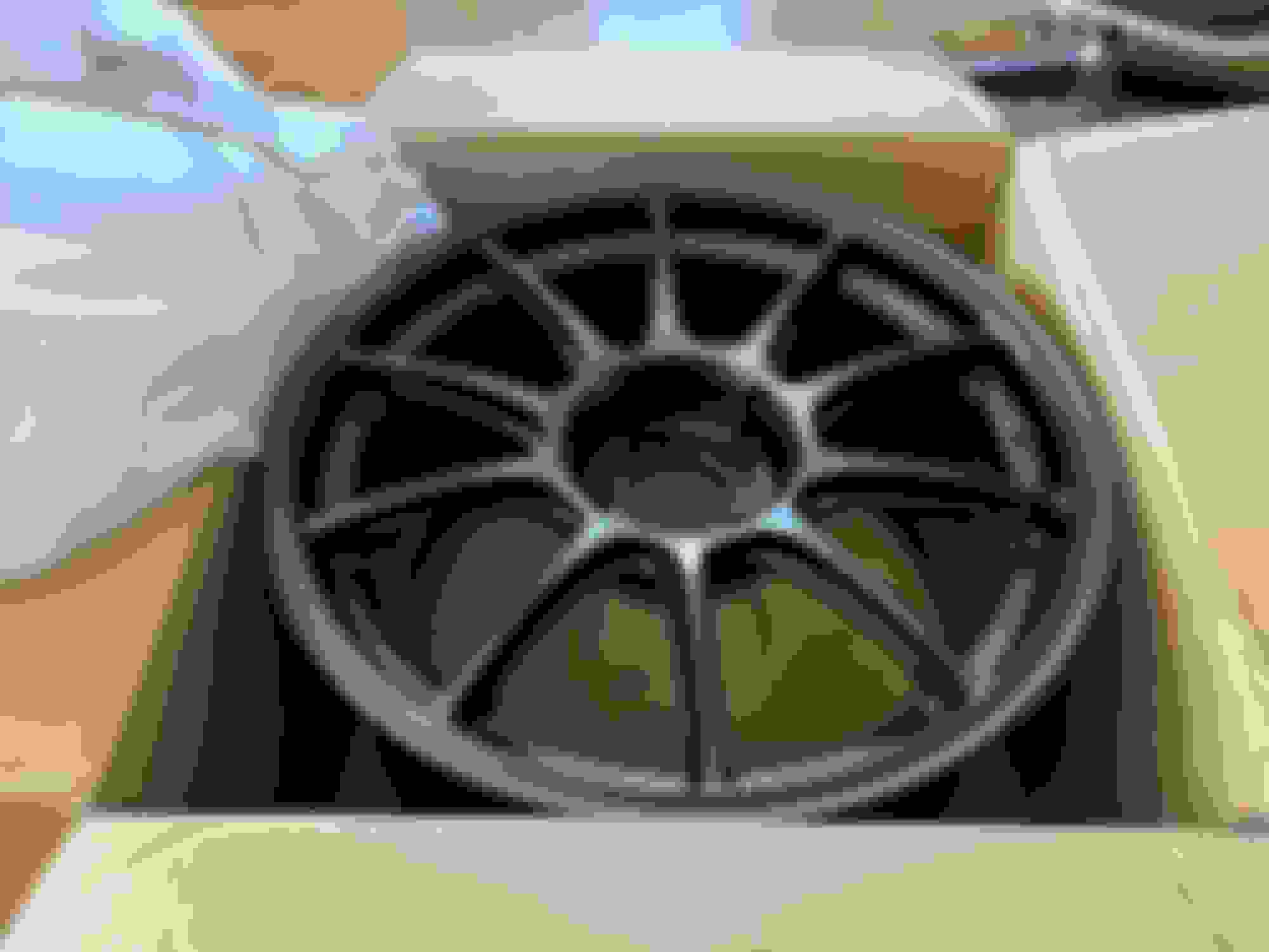
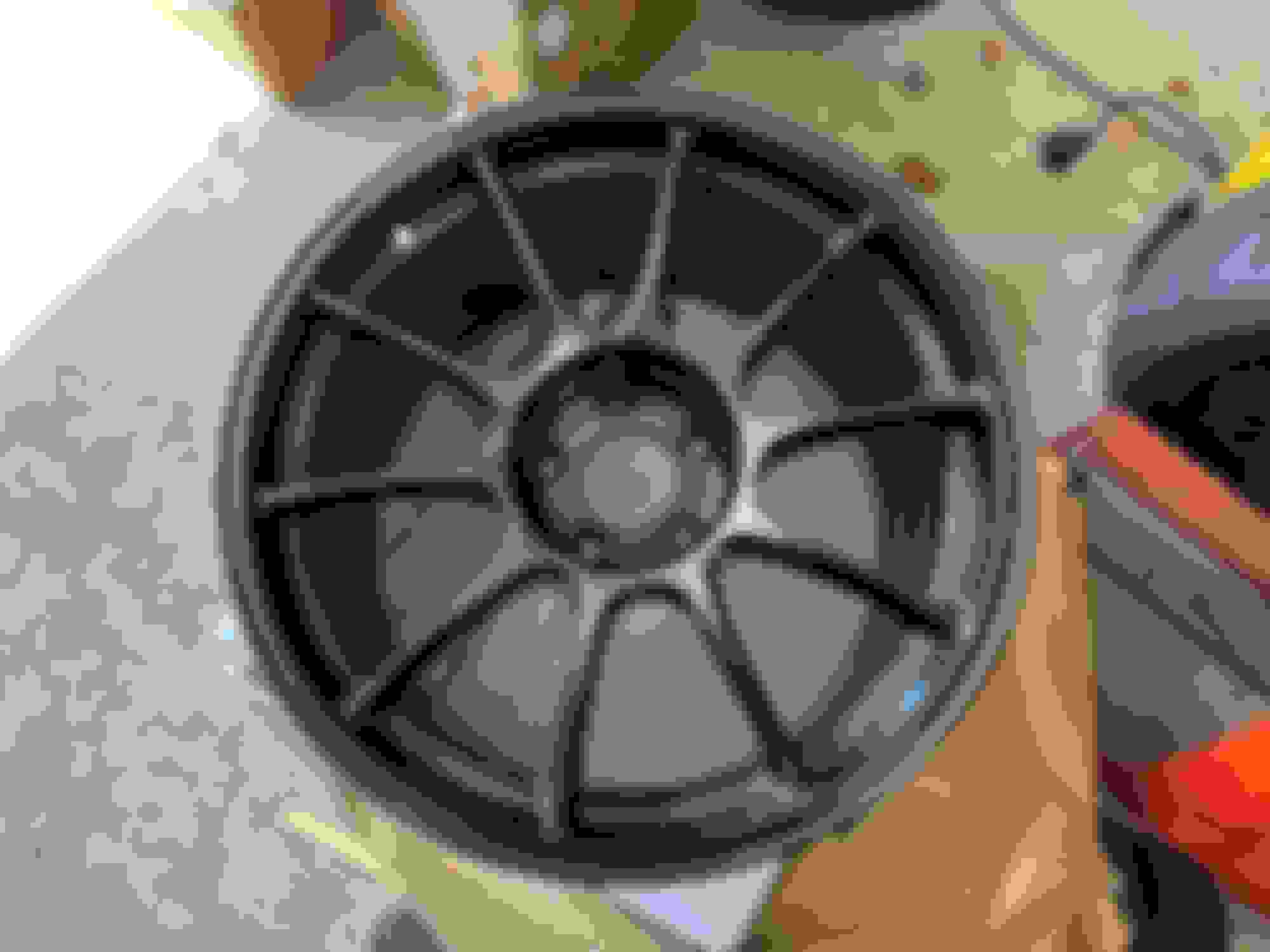
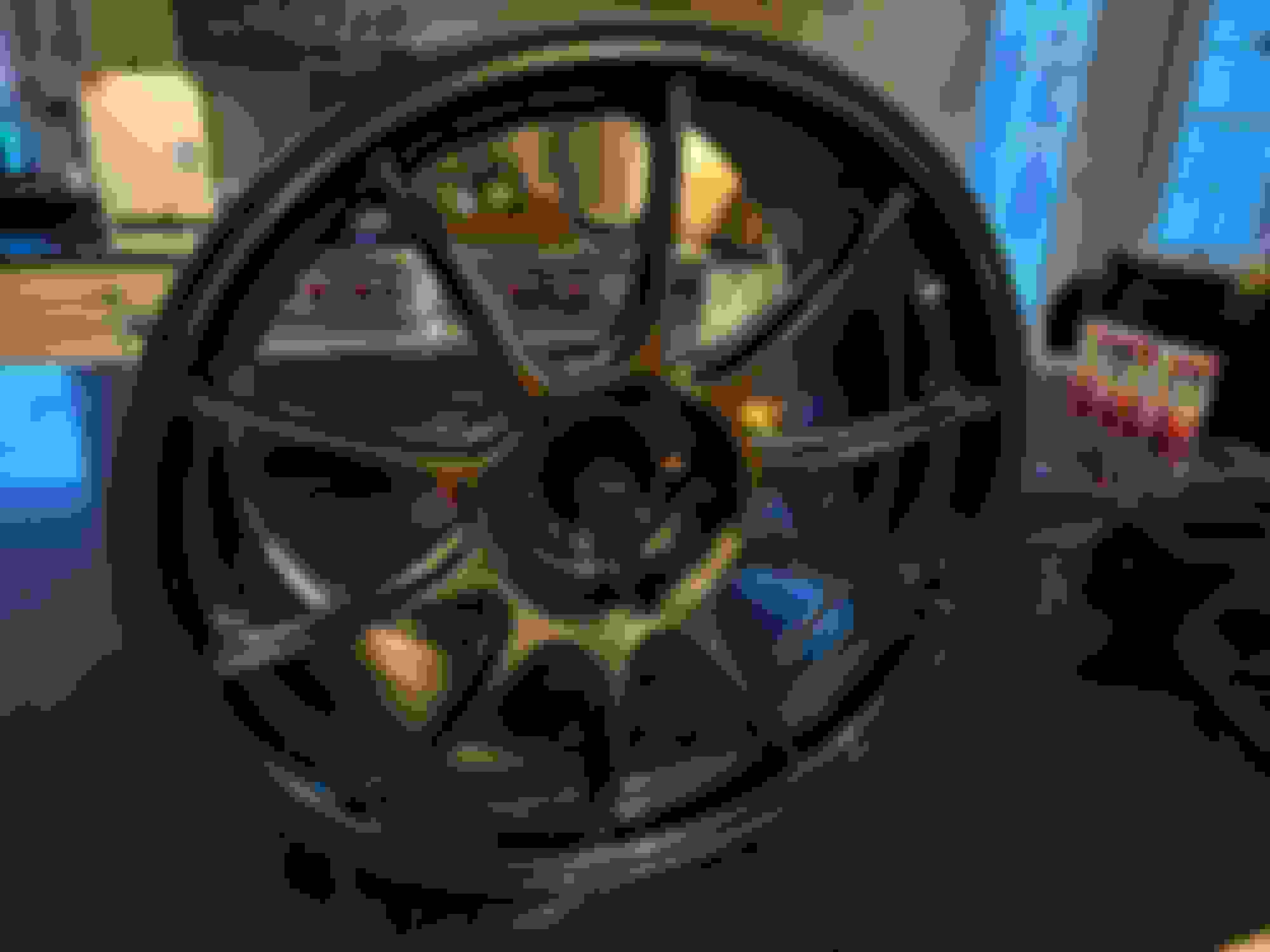
I think this photo does a decent job of showing how the color of the wheel can change depending on lighting.
From what I've read here on EvoM this seems like the widest wheel I can fit without any drama/headaches/you get the idea. I haven't mounted them on my car yet so I can't say for sure. My rear fender lips are untouched and I plan on shaving them to make room for the wheels.
These are the cast version of the TC105X. Weds also offers a forged version of the TC105X that is even lighter. Weds advertises the lower offset variants of the wheel as weighing 8.04kg (17.7lbs), the same weight as the factory BBS wheels on my car now. One of the big draws of this wheel for me was the idea that I could upsize my wheels from the stock 17x8 to 18x10 without gaining any weight. Interestingly, the +35 offset wheels that I purchased are advertised as weighing a slightly heavier 8.23kg (18.1lbs). When I received the wheels, one of the first things I did was weigh one of them. I don't have a picture of the scale but it ended up being 18.6 lbs, so I don't think their advertised weight is correct. The possibility exists that my scale is inaccurate, but since I only have one scale I can't test that.
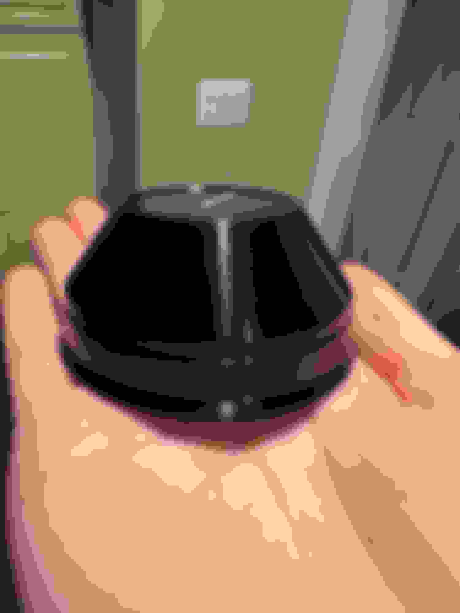
Along with the wheels I also purchased Weds' hubcentric center caps.
Individually packaged.
These are their Type I center caps with 67mm inner bore and 73mm outer bore. Turns out the Weds logo in the middle of the cap is bonded using adhesive that can melt when exposed to high temperature, so Weds warns not to use these in high performance driving.
STRUT BRACE
Carbing produces an aluminum and a titanium strut brace for our cars. Both braces have master cylinder stoppers, but only the aluminum brace can be had with the stopper on the left hand side. Their LHD braces are made to order. I waited two months for this brace to be made.
Part number on box. The L denotes that this is the LHD version of the brace.
English instructions with pictures and washers used during install.
The brace is very light. I like this brace because it is triangulated, has no flexible joints, and mounts to all three studs around each strut tower (aka the stock brace).
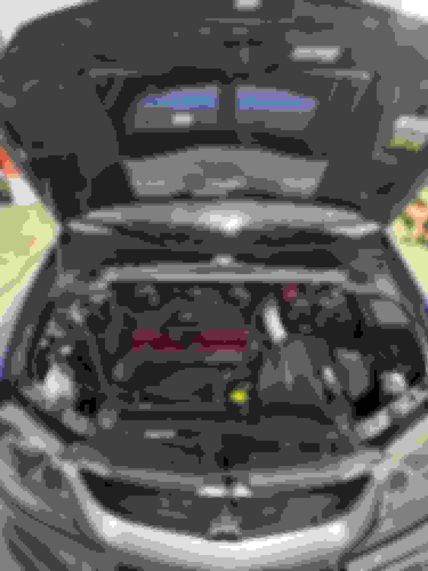
Brace installed in my engine bay.
Installation was straightforward. I placed the included washers around each strut tower stud as per the instructions and adjusted the master cylinder stopper. I did have to mess with raising and lowering each side of the car a few times to get the brace to seat on the strut towers evenly.
One thing I noticed with the new strut brace is that my car no longer creaks when I lift it into the air. With the factory brace the car would creak both when it was being lifted and being lowered back down.
I purchased Wunderladen Racing's new front engine mount and installed it on my car. I've read posts of people claiming new front engine mounts made a noticeable difference in how their cars feel and wanted to find out what one feels like.
Engine mount with included bolts.
Front view of engine mount with engraved logo.
Factory engine mount.
New engine mount vs factory engine mount.
New engine mount installed.
The center member bar that the front engine mount is bolted onto is heavy. Removal of the bar and replacing the engine mount was painless. Reinstalling the bar with the new mount installed took a few minutes of finagling to get everything to line up properly.
My stock engine mount had a very soft bushing. I was able to move the rubber around by hand. The bushing in the new engine mount is advertised as having a durometer of 85-90 and felt very stiff. When I turned on the car after installation of the new engine mount, I immediately noticed an increase in car vibration. The steering wheel was vibrating enough that I couldn't see it clearly. Turning on the air conditioning also made the vibrations worse. After a few hours of driving around I believe the engine mount had broken in because all the rough vibrations it was causing in the cabin went away. Now, the NVH is indistinguishable from before the engine mount was replaced. I never had any issues arise from my stock engine mount being too soft (at least that I'm aware of) and to me the car feels exactly the same as it did before. I wasn't sure what to expect. The Wunderladen engine mount is visually appealing, feels nice in the hand, and I'm sure is preventing the engine from moving as much as it used to, so even though I can't tell a difference I'd say I'm still satisfied.
BRAKE MAINTENANCE
Until this summer I had been using the same brake pads and fluid since 2017. I decided it was finally time to replace everything.
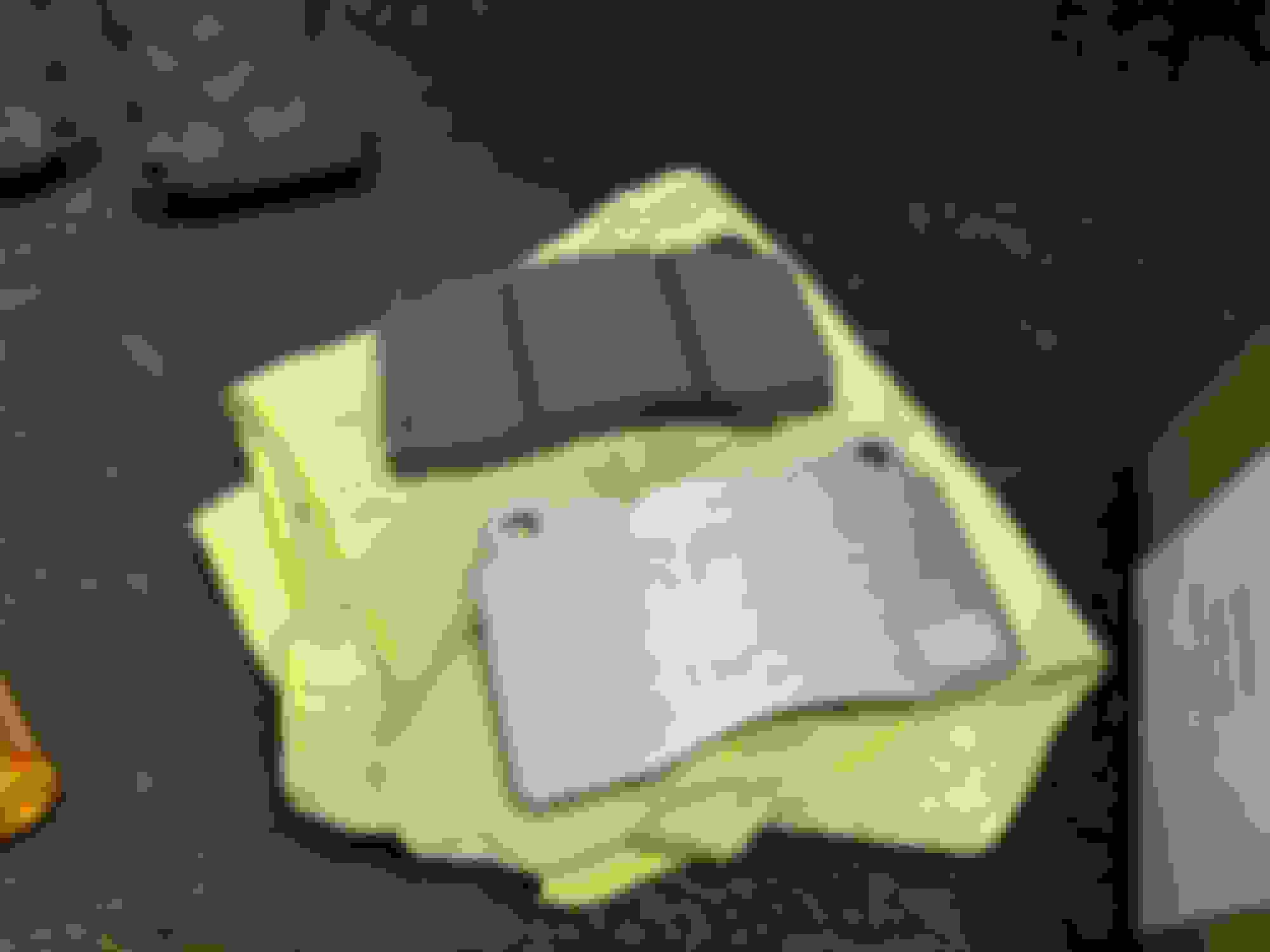
I purchased EBC RPX pads for my front brakes, EBC Blue pads for my rear brakes, and a bottle of Castrol SRF.
RPX box was trashed when I received it, but pads were fine.
EBC blue pad box
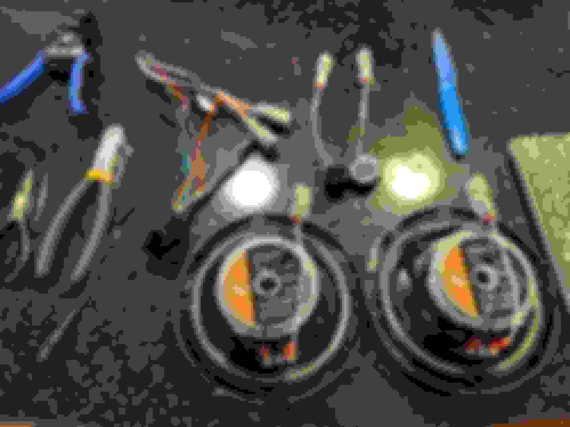
EBC brake pad lineup
Front brake caliper
Front caliper with pins and spring removed
There are two metal pins and a spring holding the brake pads in place. Use a punch to push the two pins out and the spring will fall out on its own. After that the brake pads are free to slide out of the caliper.
RPX pads
Brake grease I used
Pad shims transferred onto new pad and greased
I transferred the shims pictured above from my old pads onto my new pads. The shim directly on the brake pad had a rubberized coating while the smaller, outer shim was bare metal. I applied brake grease to the back of each brake pad, as well as in between each shim and on the back of the outer shim. With the brake grease my new brakes are completely silent.
I didn't take pictures of them, but my seven year old brake pads had a ton of meat left and were nowhere near needing replacement. My car spends 99% of its life in traffic and at low speeds so no surprise there.
Stock Bilstein strut
Picture of one of my struts from when I had the wheels off to change the brake pads. None of the struts are leaking, but they look disgusting and I don't know how deep the rust has penetrated the metal. My next big install will likely be new suspension to go along with my new wheels.
TRACK DAY
At the very last minute I was able to register for my first HPDE event with this car.
My car sitting in the paddock
DAY 1: Because I signed up for this event literally right before it happened, I didn't change my brake fluid in time for the first day. As soon as I learned a spot had opened up and I registered, I ordered Castrol SRF on Amazon, but it didn't arrive until the first day of the event. My pads were fine, but my 7 year old fluid was not (shocker). I boiled my brake fluid on my second lap of the first session. Long story short, I hung out with a friend I made and my instructor for the rest of the day before going home and flushing out my old fluid with the SRF that had arrived in the mail earlier that day.
DAY 2: My car is still running its original, 17 year old suspension and old all season tires. This was my first time really experiencing understeer and lack of grip. Because all I ever do is putt around town I have never really experienced these things. I learned that my car doesn't like to turn and doesn't like to slow down. It also didn't help that the weekend of the event it was 98 degrees out. The tires greased up instantly and my car was sliding all over the place. My instructor told me that good tires would make a huge difference and I get it now. I ended up spinning out at one point because I couldn't slow down enough entering a corner. Luckily I stayed on track and just spun in place. I also struggle to heel-toe. The steering column gets in the way of my knees (even with my lower seat brackets), making it difficult to play with the pedals.
Nonetheless I thoroughly enjoyed the experience because it taught me a lot about how the car feels and what I can do to improve it (tires). Side note: when I spun out on track, the center section of the factory undertray broke. Now that a section of the undertray is missing I'm thinking of replacing the factory undertray with something else entirely. I would love an undertray that doesn't use the screw-style clips that the factory undertray uses and is both easier and faster to remove/install. I think I'll look into making something myself.
PART COLLECTION
Finally, I've started amassing parts to be used in my car build in the distant future. Whenever a deal that I believe is too good to pass up arises, I purchase the part. So far I have:
This is a crummy photo but I purchased a set of JE ultra pistons and a set of GSC R2 cams.
SSB knuckles
1.25" SSB front knuckles and rear knuckles.
An Evo 8 5-speed trans. I was told it has 3X,XXX miles on it, but no proof. When I get the opportunity I'll open it up and look for any obvious damage.
The final big piece I have sitting around is a 94mm K1 crankshaft. I'm planning on building a 2.2 SLR.

 Jan 15, 2023, 12:51 AM


 , just not in my Evo
  .
.