
Another HFS-5 install....(picts)
 Oct 13, 2008, 09:02 PM
#1
Evolving Member
Thread Starter
Hi All of you,
After a long time working on it, I share you my HFS5 Install (Tephra mod)....
Special thanks to Tephra, Dudical26 and Jack of Trades for the inspiration...
Here we go with the tanks install...


Since It was time to work good, I take the shot to install an AFR @ the same time...

My choice regarding the DDS3 location is on the right tap (right door) to hide it but having it easy to adjust...

I decide to install nozzle right after the IC so I made a little trick on the pipe...


This is how it looks now...

My boost on WI is controlled with a solenoid + regulator
So there are 2reg: 1 for MBC on regular map (22PSI) and 1 for WI only open thru solenoid (28PSI).
Air box was a good place to make that easy...


And I also decide to wire others stuffs at the same time (flash jammer, iPod charger)
Here are my switches...with 2 leds to visualize map switching and failsafe window...

I tried to make everything thinking on failsafe window... here is my wiring (pict links to PDF file)
(probably the most useful on this thread!)

I used a dual gauge pod on the steering to have WI and AFR close to my eyes...

And this is the overview...


I first tried to use VTA but after fighting too much with stalling, I return recirculated now, even I know I will inject some water-alcohol on the turbo when BOV open but as I asked in this thread , I think it should be ok...I let you know...
I will try to add some picts when classified!!
Now I am ready to start working on maps and since I am not very confident with my ECU work, I think to win some time working with Mellon...
I 'll let you know how this works soon...
NEW UPDATED POST 18 MONTHS LATER.... HERE
Cheers,
After a long time working on it, I share you my HFS5 Install (Tephra mod)....
Special thanks to Tephra, Dudical26 and Jack of Trades for the inspiration...
Here we go with the tanks install...
Since It was time to work good, I take the shot to install an AFR @ the same time...
My choice regarding the DDS3 location is on the right tap (right door) to hide it but having it easy to adjust...
I decide to install nozzle right after the IC so I made a little trick on the pipe...
This is how it looks now...
My boost on WI is controlled with a solenoid + regulator
So there are 2reg: 1 for MBC on regular map (22PSI) and 1 for WI only open thru solenoid (28PSI).
Air box was a good place to make that easy...
And I also decide to wire others stuffs at the same time (flash jammer, iPod charger)
Here are my switches...with 2 leds to visualize map switching and failsafe window...
I tried to make everything thinking on failsafe window... here is my wiring (pict links to PDF file)
(probably the most useful on this thread!)
I used a dual gauge pod on the steering to have WI and AFR close to my eyes...
And this is the overview...
I first tried to use VTA but after fighting too much with stalling, I return recirculated now, even I know I will inject some water-alcohol on the turbo when BOV open but as I asked in this thread , I think it should be ok...I let you know...
I will try to add some picts when classified!!
Now I am ready to start working on maps and since I am not very confident with my ECU work, I think to win some time working with Mellon...
I 'll let you know how this works soon...
NEW UPDATED POST 18 MONTHS LATER.... HERE
Cheers,
Last edited by Vigman; Oct 28, 2011 at 10:01 PM.
 Oct 14, 2008, 10:34 AM
#3
Evolving Member
Thread Starter
My pleasure Mr Dudical26!
I control my boost generating a leak on the waste gate control line...
Solenoid (WI Overboost EV on schematics) activate the second pressure regulator to make the leak bigger...
I hope this picture can explain how...


I control my boost generating a leak on the waste gate control line...
Solenoid (WI Overboost EV on schematics) activate the second pressure regulator to make the leak bigger...
I hope this picture can explain how...
Last edited by Vigman; Oct 14, 2008 at 10:54 AM.
Oct 14, 2008, 01:24 PM
#5
Evolved Member
iTrader: (17)
Join Date: Nov 2005
Location: NNJ
Posts: 2,544
Likes: 0
Received 0 Likes
on
0 Posts
I see, or at least I think I do.
Its basically a dual stage boost controller using bleeder valves to bleed off air from the stock boost control system.
what confused me at first was the fact that your boost lines look just like water injection lines...... I was thinking, why is he running WI to the airbox, hehe.
thanks for explaining.
Oct 14, 2008, 01:35 PM
#6
Evolving Member
Thread Starter
(in fact what aquamist use for WI are originally pneumatic stuffs too...)
Regarding functionality, you perfectly understood!
Cheers!
Last edited by Vigman; Oct 14, 2008 at 01:37 PM.
Oct 14, 2008, 03:11 PM
#7
Former Sponsor
iTrader: (5)

Join Date: Aug 2005
Location: England
Posts: 2,236
Likes: 0
Received 0 Likes
on
0 Posts
Great innovative install indeed.
I am a bit concern about the angle of the jet. Please try a test spray - no intrusion to the spray pattern.
Those pneumatic speed controller are perfect for bleeding air. Be careful some of them are directional.
I am a bit concern about the angle of the jet. Please try a test spray - no intrusion to the spray pattern.
Those pneumatic speed controller are perfect for bleeding air. Be careful some of them are directional.
Trending Topics
Oct 14, 2008, 05:44 PM
#8
Evolving Member
Thread Starter
I have made some test connecting the nozzle directly on the pump and I made and adjust precisely the extra aluminum pipe part to obtain something like this:

Do you feel it's gonna be a problem?
I am sure to not affect the spray pattern, in fact I am just a bit concern by the fact that boost pressure will distort the spray pattern but as far as I though, I am sure it can only be better than the typical 90 degrees nozzle installation...
What do you think?
Oct 17, 2008, 12:49 AM
#9
Former Sponsor
iTrader: (5)
Join Date: Aug 2005
Location: England
Posts: 2,236
Likes: 0
Received 0 Likes
on
0 Posts
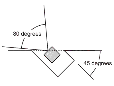
The spray angle is about 80 degress, if the devisation from the vertical is over 45 degrees, there is a change the spary may hit the side wall. Thereis not harm in testing it.
Just disconnect the green wire from the fuel injector and gropund it, you will get a full spray.
Just disconnect the green wire from the fuel injector and gropund it, you will get a full spray.
 Oct 29, 2008, 09:08 PM
#11
Evolving Member
Thread Starter
Thank you Richard.
I made a new test running pump and injector directly and it looks fine!
Sorry if I took some time to answer but pipe/injector is not easily accessible ;-(
I am now waiting for my APS twin vent BOV to start fine tune with Chris T.
Will let you know...
Cheers!
I made a new test running pump and injector directly and it looks fine!
Sorry if I took some time to answer but pipe/injector is not easily accessible ;-(
I am now waiting for my APS twin vent BOV to start fine tune with Chris T.
Will let you know...
Cheers!
Oct 30, 2008, 07:54 AM
#13

Very clean install! I really like your UICP injection point and the install in the trunk is exceptionally clean. The method of boost control you are using is a little old-school, but it definitely works! The mount on the airbox looks clean, but you may consider routing the bled air back into the intake pipe, after the MAS, not before it (since the air is already read by the MAS.
